Accessories
7.2 Brake Relay
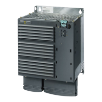
PM250 Power Module
Hardware Installation Manual, 09/2012, A5E01003502B AD
67
7.2 Brake Relay
The Brake Relay is designed to provide the interface between the Power Module and the
brake solenoid of a motor. There are two types of Brake Relays:
● Brake Relay – this provides the basic braking control function.
● Safe Brake Relay – this provides for the braking control function within a safety integrated
system. To adhere to the requirements of a safety integrated system, the Safe Brake
Relay has been designed to allow a variable voltage to be given to the Safe Brake Relay
to allow the system to determine if the Safe Brake Relay is functioning correctly without
actually activating the braking function.
Mounting the Brake Relay
The Brake Relay can be panel mounted, wall mounted or mounted on the shield connection
kit.
For more information see http://support.automation.siemens.com/WW/view/de/23623179
Connecting the Brake Relay to the Power Module
Connect one end of the cable form to the Brake Relay.
Two cable form with different lengths are provided with the Brake Relay. Choice the
adequate length of the cable depending on the frame size of the Power Module and on the
mounting location of the Brake Relay.
Brake Relay Safe Brake Relay
*URXQG(DUWK
)O\LQJOHDGWR
3RZHU0RGXOH
&RQQHFWLRQWREUDNHFRLO
LQVLGHWKHPRWRU
&RQQHFWLRQWR
H[WHUQDO9VXSSO\
)O\LQJOHDGWR
3RZHU0RGXOH
&RQQHFWLRQWREUDNHFRLO
LQVLGHWKHPRWRU
The Brake Relay control connector is marked as "CTRL"
Connect the other end of the cable form to the Power Module
Siemens Parts