230 / 244
Siemens Standard application AHU CE1P3977en_02
Building Technologies Appendices 01.02.2010
20 Appendices
20.1 Point tables
As a matter of principle, we recommend the following configuration procedure:
1. During configuration (Configuration 1 and Configuration 2) all required I/Os in
the table must be executed using the following sample.
2. Clean up the tables prior to starting I/O configuration.
3. Conduct I/O configuration per the table.
This ensures that
– The plant on the basis controller and the planned extension modules fit.
– It is evident at all times which terminals used for the required inputs and outputs.
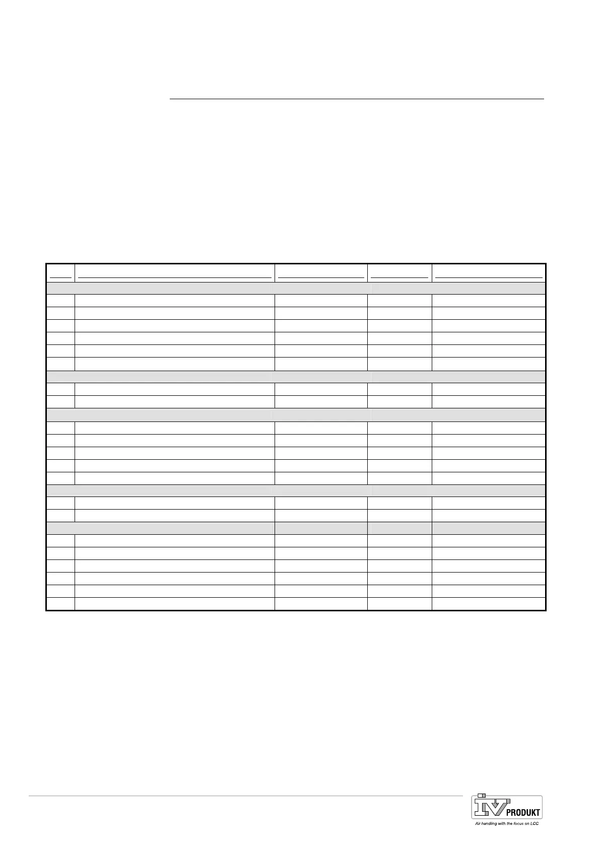
Hardware assignment for the basis controller POL683x
IO Function IO type Connection Comments
Digital outputs
DO1 Digital T6 (Q13,Q14)
DO2 Digital T6 (Q23,Q24)
DO3 Digital T6 (Q33,Q34)
DO4 Digital T6 (Q43,Q44)
DO5 Digital T7 (Q53,Q54)
DO6 Digital T7 (Q63,Q64)
Analog outputs
AO1 0...10 V DC T3 (Y1,M)
AO2 0...10 V DC T3 (Y2,M)
Binary inputs
DI1 Digital T4 (D1,M)
DI2 Digital T4 (D2,M)
DI3 Digital T4 (D3,M)
DI4 Digital T4 (D4,M)
DI5 Digital T4 (D5,M)
Universal inputs
X
1
T2 (X1,M)
X2 T2 (X2,M)
Universal inputs / outputs
X3 T2 (X3,M)
X4 T2 (X4,M)
X5 T2 (X5,M)
X6 T2 (X6,M)
X7 T2 (X7,M)
X8
– Universals I/Os X1 and X2 can be configured exclusively as inputs (digital,
Ni1000, Pt1000, NTC10K, 0-10V DC).
– Universals I/Os X3 – X8 can be configured as inputs (digital, Ni1000, Pt1000,
NTC10K, 0-10V DC) or outputs 0-10V DC.
Basis controller
Notes
Basis Document Siemens Climatix Control System
BDCX.100820.01GB
Page 230
 Loading...


