PLACING THE REGULATOR IN SERVICE
Page 9
The following checks will be useful in assuring the regulator is
ready for use. The list cannot be all inclusive; careful at-
tention on the part of a qualified operator remains imperative.
BEFORE CONNECTING
• Check oil level at oil sight window. If low, add sufficient oil
(ASTM D-3487 Type II) to bring to desired level.
• Check oil dielectric strength per ASTM D 877. If found
below 25kV, oil should be changed or reconditioned.
Reference ANSI C57.106-2002. Note: Oil tests are not
required for new equipment.
• Perform insulation power factor test per ANSI C57.15.
Maximum value is 2.0%.
• Verify from the nameplate that the unit is connected for the
proper output voltage, motor voltage and control panel
voltage.
• Assure that the regulator is on the neutral tap position.
This should be accomplished by observing the position
indicator pointer and by powering the control from a 120V
external source and observing the Neutralite
TM
to be
illuminated.
BEFORE CONNECTING
• Identify 'S', 'L' and 'SL' bushings on the cover. Make elec-
trical connections per the appropriate installation diagrams,
page 4, first connecting 'SL' bushing.
• Set Vari-Amp
TM
limits on position indicator, if necessary.
See Page 11.
• Set Accu/Stat
TM
Control as desired. See Accu/Stat
TM
instruction manual.
SWITCHING “ON-LINE”
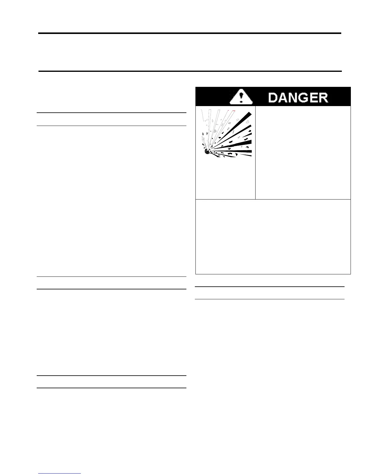
• Improper by-pass operation will result in explosion
and fire hazard. Will cause serious injury, death or
equipment damage.
• Do NOT place into service unless tap-changer is in
neutral position AND control panel is properly
disabled.
Improper By-Pass operation will
result in explosion and fire hazard.
Will cause serious injury, death or
equipment damage.
To Prevent:
Do NOT install OR remove from
service unless Tap Changer is in
neutral position AND Control Panel
is properly disabled to prevent tap
changes while in By-Pass
configuration. Read Operators
Manual before attempting to By-
Pass this Regulator.
Follow instructions to place into service:
1. Place the Auto/Manual switch in the By-Pass position
2. Place the Raise/Lower switch in "Off"
3. Make certain regulator is in neutral (N) position
4. Turn voltage power source switch to "Off"
5. Remove power fuse
6. Close, sequentially, the source and load switches
7. Open the bypass switch
8. Visually observe that bypass circuit has opened
9. Replace power fuse
10. Place voltage power source switch to "Normal."
CHECKING REGULATOR OPERATION
1. Refer to applicable Accu/Stat
TM
Control instruction
manual.)Turn the Tap Control switch to MANUAL.
2. Run the tapchanger in the lower direction, at least until
the control is observed to go out of band "LOW".
3. Turn the Tap Control switch to AUTO. After a time delay,
the regulator will return to an "IN" band condition.
4. Turn the Tap Control switch to MANUAL.
5. Run the tapchanger in the raise direction, at least until the
control is observed to go out of band "HIGH".
6. Turn the Tap Control switch to AUTO. After a time delay,
the regulator will return to an "IN" band condition.
 Loading...