30 / 94
Siemens RDF800KN.., RDF800KN/VB, RDD810KN/NF Basic documentation CE1P3174en
Smart Infrastructure 2020-02-21
3.4.3 Applications for heat pump systems (RDF800KN..,
RDF800KN/VB only)
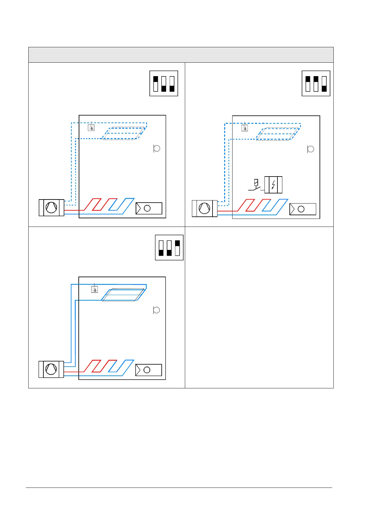
Application and output signal, DIP switches, diagram
· 1-stage compressor On/Off
(heating or cooling)
1
ON
2 3
· 1-stage compressor with electric
heater
(heating or cooling) On/Off
1
ON
2 3
N1
T
B1
T
D3
N1T
E1
B1
T
D3
· 1-stage compressor On/Off
(heating and cooling)
1
ON
2 3
N1
T
B1
T
D3
N1 Thermostat
Terminal Y1: Heating or heating/cooling
Terminal Y2: for cooling (H&C)
B1 Return air temperature sensor or external room
temperature sensor (optional)
E1 Electric heater D3 Dew point sensor

 Loading...