40 / 94
Siemens RDF800KN.., RDF800KN/VB, RDD810KN/NF Basic documentation CE1P3174en
Smart Infrastructure 2020-02-21
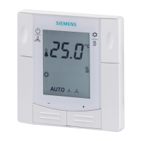
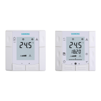
The diagrams below show the control sequence for 2-position.
Heating mode
(automatic changeover = heating or heating only)
Cooling mode
(manual/auto. changeover = cooling or cooling
½ SDH
1
0
½ SDH
w
T[°C]
V1
½ SDH ½ SDH
E1
w
D
½ SDC
0
½ SDC
w
T[°C]
V1
½ SDH
½ SDH
E1
x
dz
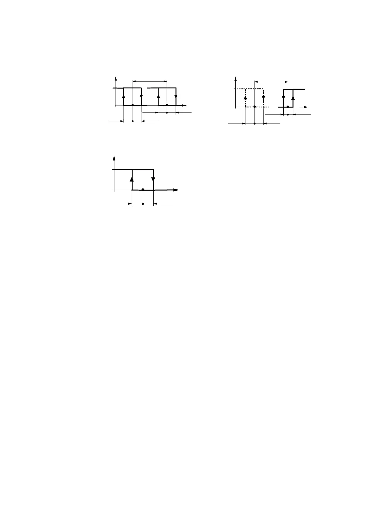
Heating mode with manual changeover (P01 = 2) (manual changeover = heating)
½ SDH
0
½ SDH
w
T[°C]
E1
T[°C] Room temperature
W Room temperature setpoint
V1 Control command "Valve" or "Compressor"
E1 Control command "Electric heater"
SDH Switching differential "Heating" (P30)
SDC Switching differential "Cooling" (P31)
X
dz
Dead zone (P33)
w
D
Setpoint differential (P34)
· The diagrams only show the PI thermostat’s proportional action.
· For the fan sequence see section 3.8.
· For better temperature control performance with 2-position electric heater, we
suggest you set the switching differential heating (P30) to 1 K.
Refer to sections 3.4, 3.6.1, and 3.7.
On/Off control
Control sequence
ON/OFF output
Setting the sequence

 Loading...