RUGGEDCOM RX1501
Installation Guide
Chapter 2
Installing the Device
Connecting the Failsafe Alarm Relay 13
Section 2.3
Connecting the Failsafe Alarm Relay
The failsafe relay can be configured to latch based on alarm conditions. The NO (Normally Open) contact is
closed when the unit is powered and there are no active alarms. If the device is not powered or if an active alarm
is configured, the relay opens the NO contact and closes the NC (Normally Closed) contact.
NOTE
Control of the failsafe relay output is configurable through ROX II. One common application for this
relay is to signal an alarm if a power failure occurs. For more information, refer to the ROX II User
Guide for the RX1501.
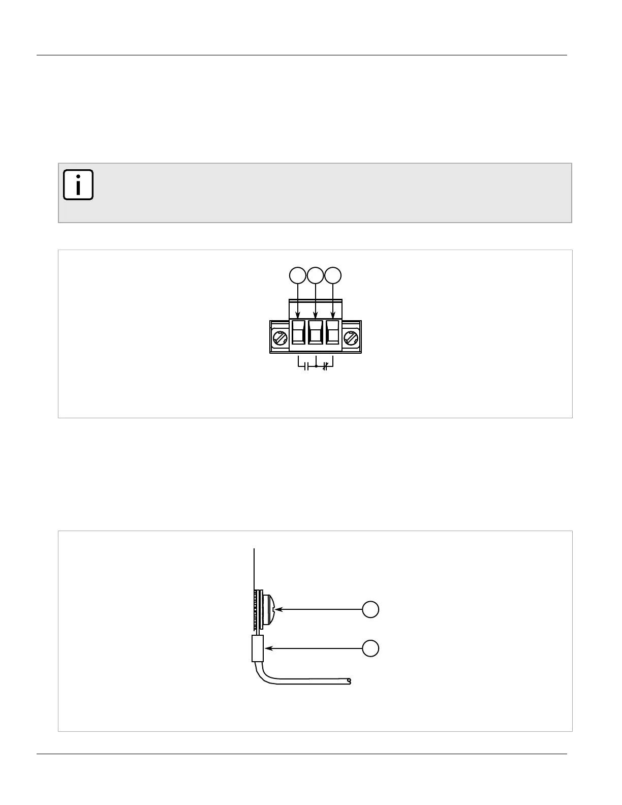
The following shows the proper relay connections.
Figure 10: Failsafe Alarm Relay Wiring
1. Normally Open 2. Common 3. Normally Closed
Section 2.4
Grounding the Device
The RX1501 chassis ground terminal uses a #10-32 screw. It is recommended to terminate the ground
connection with a #10 ring lug and torque it to 3.4 N·m (30 lbf·in).
Figure 11: Chassis Ground Connection
1. #10-32 Screw 2. #10 Ring Lug

 Loading...