RUGGEDCOM RX1501
Installation Guide
Chapter 1
Introduction
Ports, Controls and Indicator LEDs 3
• Input voltage ranges: 13-36 VDC and 37-72 VDC or 85-264 VAC and 88-300 VDC for worldwide operability
• CSA/UL 60950-1 safety approved to 85 °C (185 °F)
Section 1.2
Ports, Controls and Indicator LEDs
The RX1501 features various ports, controls and indicator LEDs on the front panel for configuring and
troubleshooting the device.
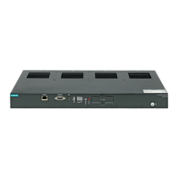
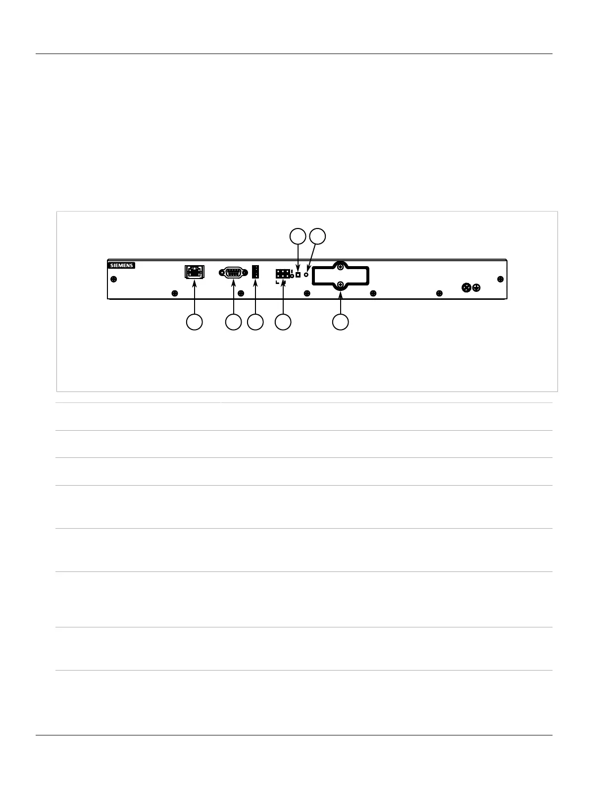
Figure 1: Front Panel
1. Management Port 2. RS232 Serial Console Port (DB9) 3. Utility USB Port 4. Port Status Indicator LEDs 5. Alarm Indicator LED
6. Lamp Test/Alarm Cut-Off (LT/ACO) Button 7. Compact Flash Card Port
Management Port This 10/100Base-T Ethernet port is used for system management that is out-of-band from
the switch fabric.
RS232 Serial Console Port This port is for interfacing directly with the device and accessing initial management
functions.
Utility USB Port The USB port can be used to upgrade the ROX II software or install files, such as
configuration files and feature key files.
Lamp Test/Alarm Cut-Off (LT/ACO) Button This button performs two functions:
• Press and hold this button to test all indicator LEDs
• Press and release this button to acknowledge an active alarm
Power Module Indicator LEDs These LEDs indicate the status of the power modules.
• I = The power supply is receiving power
• O = The power supply is supplying power
Port Status Indicator LEDs These LEDs indicate when ports are active.
• Green = OK
• Orange = Warning alert
• Red = Configuration error
Alarm Indicator LED The alarm indicator LED indicates when an alarm condition exists.
• Green = Alarms cleared/acknowledged
• Red = Alarm
Compact Flash Card Port This port houses the 1 GB compact flash card that contains active and backup installations
of ROX II, along with the configuration database and other system data.
 Loading...