Siemens PM240-2_EN_rev00-30082019.docx 7-3
7.5 SIEMENS S120 CONTROL UNIT ELECTRICAL WIRING
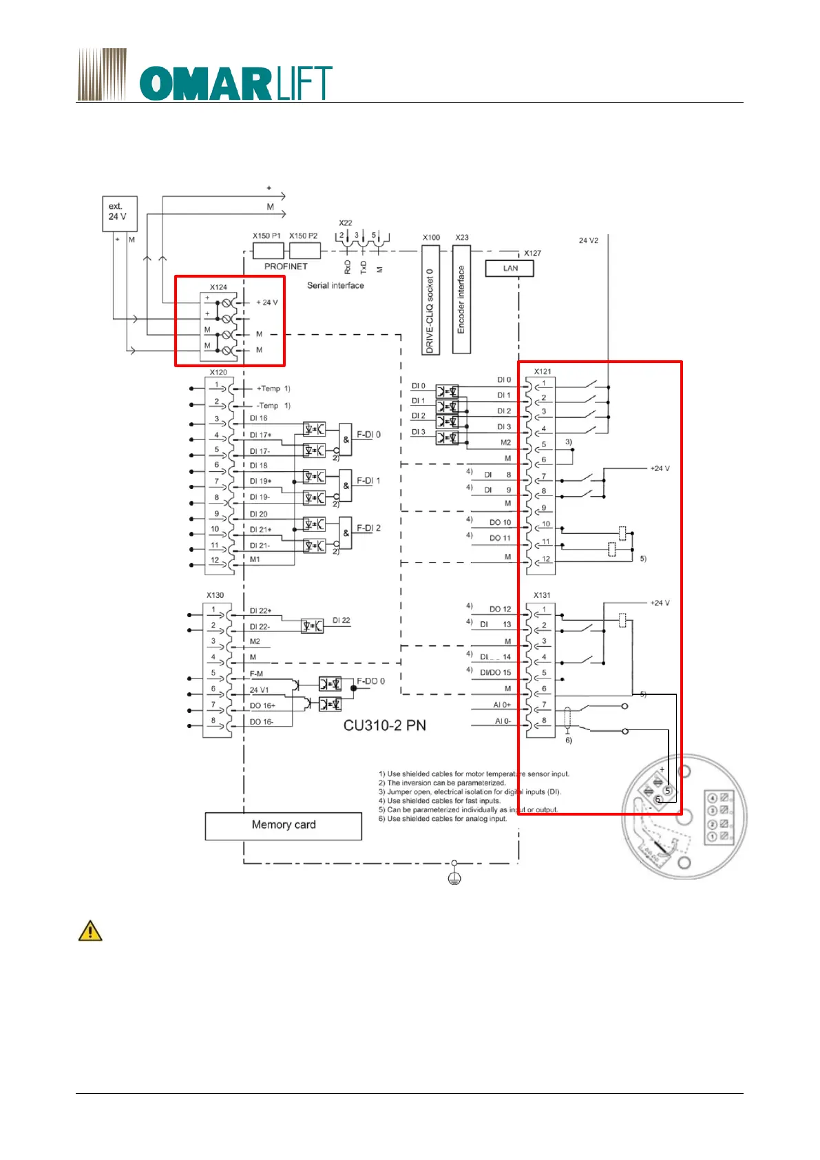
Below is a diagram for the execution of wiring for inverter Control Unit (CU) with all electrical connections.
All supplies at 24V are in continuous current (DC) rectified.
Highlighted in red, the wirings you have to perform.
Figure 17 Connection example CU310-2 PN without safety function
The Input port X131.2 could be used for reset automatically some system faults by the main switch
board, on the base of its evaluation.
X121.7-Emergency and X131.4-Short Floor, allow to set specific reduced high speed that will be used in
place of the standard value of high speed.
X121.7 has to be used as a +24V command to reduce the power used in condition of UPS feeding (for
example in emergency conditions activated by the fire fighters). See paragraph 11.4.4.
X121.1 Upwards
X121.2 High Speed
X121.3 Enable
X121.4 Downwards
X121.7 Emergency
X121.8 Inspection
X121.10 Contactors
X121.11 EVD
X131.1 Fault (0=Fault)
X131.2 Reset Fault
X131.4 Short Floor
X131.7 +24V
X131.8 SENECA
Amplifier for
PT100 Thermocouple

 Loading...


