CP 1243-7 LTE
Operating Instructions, 01/2015, C79000-G8976-C381-01
27
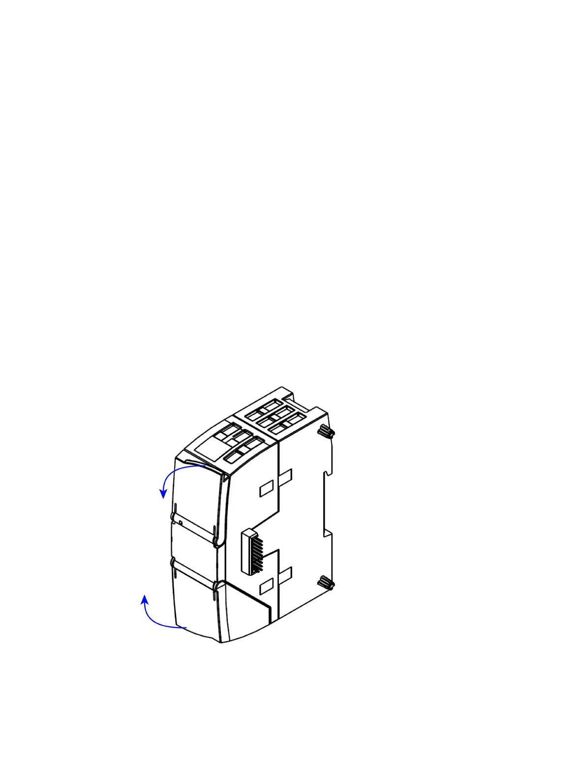
Opening the housing
Location of the display elements and the electrical connectors
The LEDs for the detailed display of the module statuses are located behind the upper cover
of the module housing.
The socket for the power supply is located on the top of the module.
The connector for the external antenna is located on the bottom of the module.
The compartment for inserting the SIM card is located behind the upper hinged cover of the
module.
Open the upper or lower cover of the housing by pulling it down or up as shown in the
illustration. The covers extend beyond the housing to give you a grip.
Figure 2-1 Opening the housing

 Loading...


