EasyManuals Logo

Siemens S7-400 User Manual

Siemens S7-400
316 pages
To Next Page IconTo Next Page
To Previous Page IconTo Previous Page
Page #137 background imageLoading...
Page #137 background image
Networking
5-19
S7-400 and M7-400 Programmable Controllers Hardware and Installation
A5E00069481-04
5.6 Bus Connectors
Purpose of the Bus Connector
The bus connector is used to connect the PROFIBUS-DP bus cable to the MPI or
PROFIBUS-DP interface. In this way, you establish the connection to other nodes.
There are two different bus connectors:
Bus connector without PG connector
(6ES7 972-0BA20-0XA0)
Bus connector with PG connector
(6ES7 972-0BB20-0XA0)
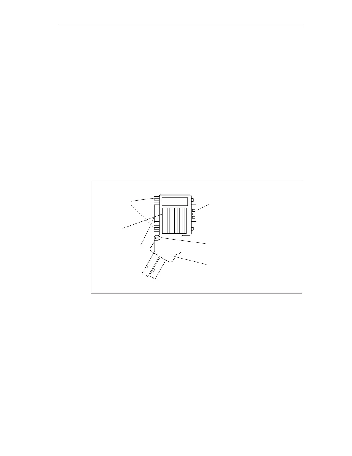
Appearance (6ES7 972-0B.20 ...)
Screws for
mounting on
station
PG connector (only with
6ES7 972-0BB20-0XA0)
9-pin sub. D male connector
for connection to MPI or
PROFIBUS-DP interface
Housing screw
Switch for
terminating
resistor
Clamp hinge for vertical
or 30° cable routing
Figure 5-11 Bu s connector

Table of Contents

Other manuals for Siemens S7-400

Questions and Answers:

Question and Answer IconNeed help?

Do you have a question about the Siemens S7-400 and is the answer not in the manual?

Siemens S7-400 Specifications

General IconGeneral
Product type designationS7-400
Protection ClassIP20
CPU TypeVarious (e.g., CPU 412, CPU 414, CPU 416, CPU 417)
Digital InputsDepends on configuration and modules used
Digital OutputsDepends on configuration and modules used
Analog InputsDepends on configuration and modules used
Analog OutputsDepends on configuration and modules used
Communication InterfacesMPI, PROFIBUS, PROFINET
Programming LanguagesSTEP 7 (STL, LAD, FBD, SCL, GRAPH)
Power Supply24V DC or 120/230V AC (depending on the power supply module).
Operating Temperature0°C to 60°C
Relative Humidity5% to 95% (non-condensing)
RedundancySupported (with specific CPUs and configurations)
Mounting TypeRack mounting
MemoryUp to several MB (depends on CPU model)

Related product manuals