Siemens Siemens
Siemens Siemens
Siemens
IndustryIndustry
IndustryIndustry
Industry
,,
,,
,
Inc. Inc.
Inc. Inc.
Inc.
Building Building
Building Building
Building
TT
TT
T
ecec
ecec
ec
hnologies Dihnologies Di
hnologies Dihnologies Di
hnologies Di
visionvision
visionvision
vision
P/N 315-050537-3
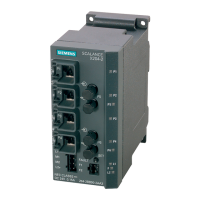
INTRODUCTION The Model Scalance X204-2 Multimode and X204--2LD Single
Mode Ethernet Fiber Switch (as shown in Figure 1) from
Siemens Building Technologies, Inc. is used to maintain a Style
7 ring or Style 4 (Class B) wiring for communications between
all buildings and Siemens Building Management Systems (Fire
Command Centers within a FVNET campus, NCC, Desigo CC,
Cerberus DMS). Both Style 7 and Style 4 perform all required
monitoring of the health of the network. Style 7 wiring will
automatically ‘heal’ the ring when a break or other failure is
encountered. The failure is reported via SNMP (Simple
Network Management Protocol).
The fiber switch obtains its power from a 24V UL Listed for
Fire Application, Power Limited - Regulated Power Supply. It
provides connectors for the fiber cable and four RJ45
100BaseT network connections.
In Style 7, the fiber switch that is connected to the primary
NCC is designated as the ring master. There is no difference
in installation, configuration, and operation of single mode or
multimode fiber optic switches except the type of fiber used.
INSTALLATION
Remove all system power before installation, first battery then AC. (To power up,
connect the AC first, then the battery.)
Mounting on VNT-MP The fiber switch mounts on a bracket in the lower left corner of the VNT-MP mount-
ing plate as shown in Figure 2. To mount the fiber switch on the bracket, place the
bottom edge of the fiber switch cutout on the bottom edge of the rail between the
VNT-MP and the standoff and then snap the top edge of the fiber switch cutout on to
the top edge of the rail. Refer to Figure 3 for the mounting detail.
Fiber Switch Ethernet Connections
Installation Instructions
Model Scalance X204-2 Multimode and X204-2LD Single Mode
Ethernet Fiber Switch
Figure 1
Scalance X204-2/
X204-2LD Ethernet
Multimode
Fiber Switch
OUT
L2+
Figure 2
Fiber Switch Mounting on VNT-MP
Figure 3
Fiber Switch Mounting Detail
VNT-MP
VNT-PS
FIBER
SWITCH
XND
VNT
RAIL FOR
FIBER SWITCH
MOUNTING
STANDOFF
TO KEEP
FIBER
SWITCH
IN PLACE
BRACKET FOR
MOUNTING
FIBER SWITCH
1. PLACE BOTTOM EDGE OF
FIBER SWITCH GROOVE ON
BOTTOM EDGE OF RAIL.
2. SNAP TOP EDGE OF
FIBER SWITCH GROOVE
ON TO TOP EDGE OF RAIL.