B. Installation instructions:
1. Drill mounting holes located per customer construction standards.
2. Install the mounting bolts in the holes (mounting bolts are not furnished) and mount
the switch.
NOTE: Be very careful when locating the switch on the crossarm or steel structure
and when tightening the mounting bolts. Tighten the bolt until the split washer is
flattened.DO NOT TWIST OR BOW THE SWITCH BASE.
3. Insert the interrupters and twist into the locked position (if required).
NOTE: Be very careful when handling the switch and interrupter not to damage either
assembly.
C. Operational check-out instructions:
1. SWITCHES ARE FULLY ADJUSTED AND INSPECTED before they leave the factory.
There should not be any need to adjust the switch unit.
2. The following checks should be performed on all switches to verify proper operation
of the switches and interrupters (if required). This will be done manually.
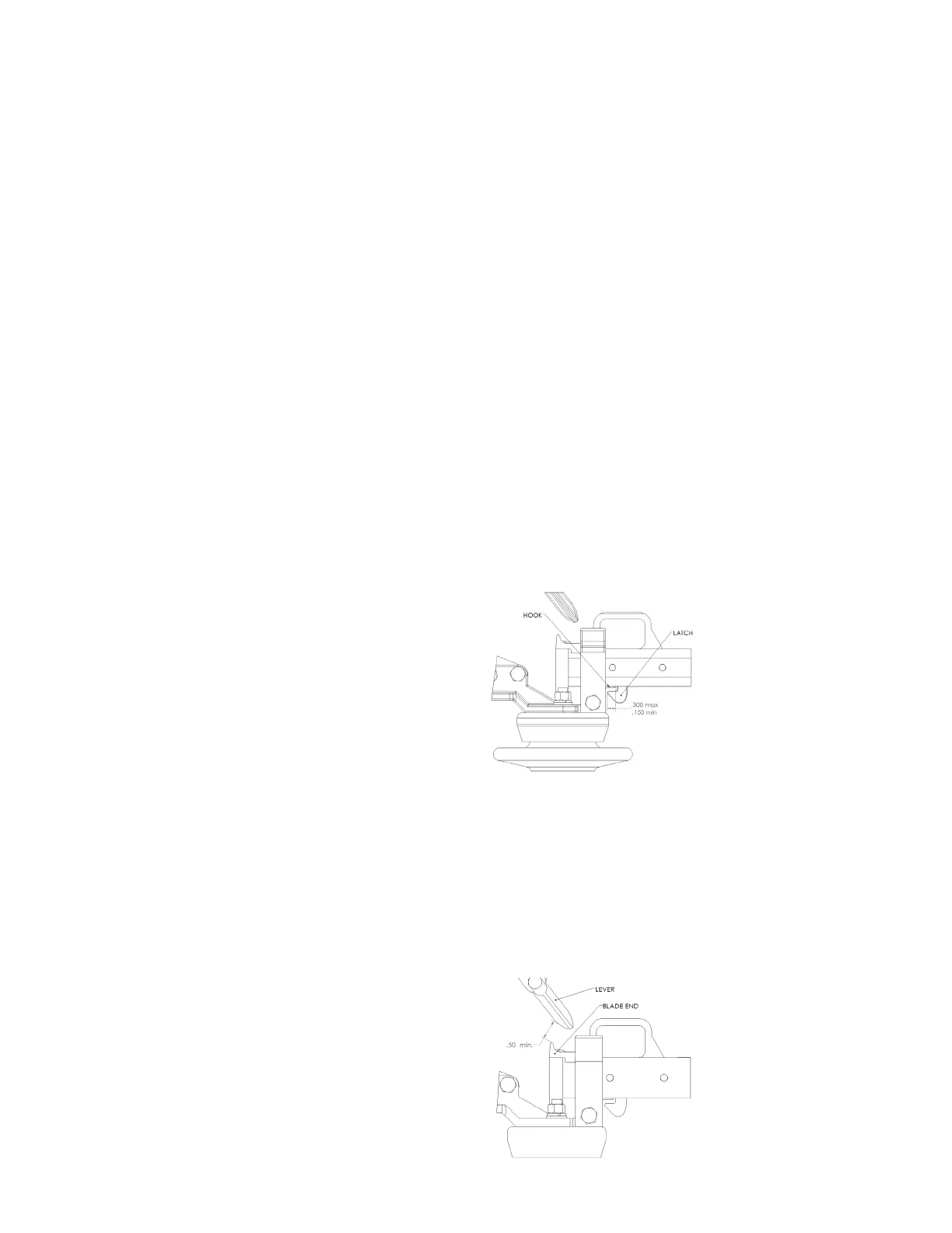
a. Close the switch fully. The latch should overlap the hook by 0.150 (min.) to
0.300 (max) of an inch, and the latch should be below the hook as shown
on the right.
NOTE: If the switch is not equipped with interrupters, proceed to step 4 below.
If the switch is equipped with interrupters, make the following checks:
b. With the switch fully closed and the interrupter cocked (set to trip), the lever should
be above the blade end as shown below with no metal-to-metal contact between the
interrupter’s lever and the blade end casting.
c. Slowly open the switch and be sure that the following operations occur:
Hookstick disconnect switches (types SE, SEL, SER, LER, E, EF, B-1, B-2, EH, EHL, and EHTT) Instruction Manual
5