Installation Instructions
Mounting
1. To ensure safe installation, verify that the surface of the mounting location is level.
2. Mount the Electronic Bypass Option vertically with the SED2 operator panel, Electronic Bypass Option
keypad, and disconnect accessible.
Depth
With
Handle
9.6 (24)
Depth
With
Handle
12.2 (31)
Depth
With
Handle
9.6 (24)
13.2
(34)
34
(86)
48
(122)
11.5
(29)
Frame Size
A and B
Frame
Size C
12.4
(31)
10.5 TYP
(27)
10.6
(27)
11 TYP
(28)
20.8
(53)
Depth
With
Handle
10.4 (26)
57.5
(146)
Frame
Size D
19.9
(51)
11.5 TYP
(29)
1.5
(3.8)
1.5
(3.8)
2
(5)
2
(5)
4
(10)
3.4
(8.6)
57.5
(146)
45.5
(116)
Depth
17.4
(44)
Frame Size FFrame Size E
20.8
(53)
58.5
(149)
19.9
(51)
10 TYP
(25)
5.5
(14)
3
(7.6)
2.9
(7.4)
2.9
(7.4)
1
(2.5)
VFD0127R1
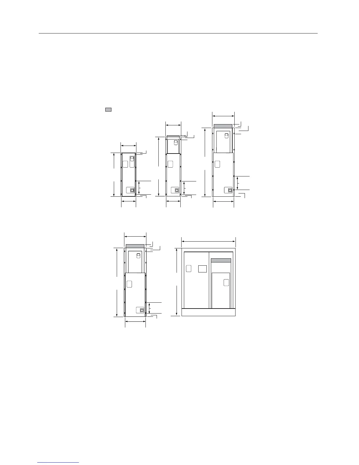
= Protective Shield
NOTE: It is recommended to leave 6 inches (15 cm) around the top and sides of the unit.
Figure 5. Electronic Bypass Option Dimensions in Inches (Centimeters).
Siemens Building Technologies, Inc. 9