SED2 VFD Electronic Bypass Option Operating Instructions
Settings
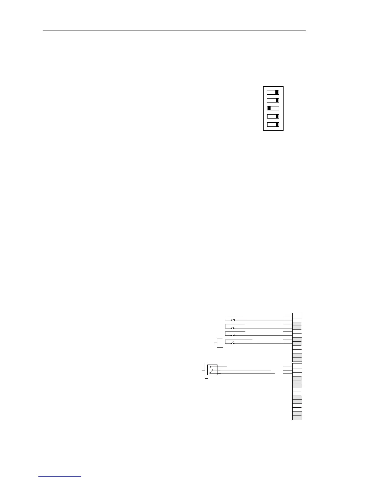
The Interlock feature requires that Controller board DIP Switch 3
is set ON.
NOTES:
1. The Interlock Start Logic Enabled indicator is on steady.
2. Example assumes hardwired start is in auto. If other,
modify P0732 as appropriate.
For proper Interlock operation, set the following SED2
parameters:
VFD0118R1
ON
12
5
34
12 534
ON
OFF
SW1
Customer
Proof
Power to
Customer
Device
Programmable Output, NO
COM
NC
DIGITAL OUTPUTS
DIGITAL INPUTS
J2
J1
13
14
15
16
17
18
19
20
21
22
23
24
25
26
1
2
3
4
5
6
7
8
9
10
11
12
Remote Start Input
Remote Safety #1
Remote Safety #2
Interlock Start
P0700 in000 = 2
Digital input that is the start command in the auto mode (from the damper end switch)
•
•
•
•
•
•
•
P0700 in001 = 2
Digital input that is the start command in the hand mode (from the damper end switch)
P0701 in000 = 99 and P0701 in001 = 99
Initiate BiCo
P0702 in000 = 3 and P0702 in001 = 3
P0732 in000 = 722.0
Tells the drive through BiCo that instead of starting the drive in auto mode when the
Remote Start input closes, it should close the SED2 Relay.
P0732 in001 = 19.0
Tells the drive through BiCo that instead of starting the drive in hand mode when the
green Start button is selected, it should close the SED2 Relay.
P0704 in000 = 1 and P0704 in001 = 1
NOTE: For a complete description of BiCo, see the SED2 VFD Startup, Operation, and
Maintenance Manual (125-3201).
Wiring Example for Interlock
VFD0115R2
22 Siemens Building Technologies