SED2 VFD Electronic Bypass Option Operating Instructions
Electrical Installation
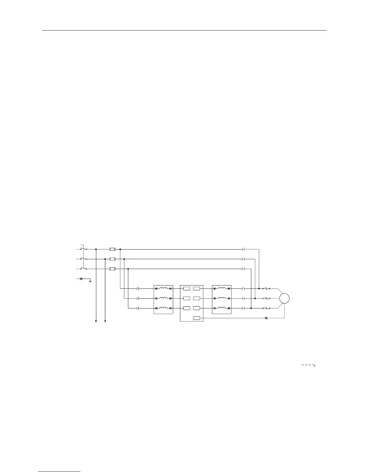
See Figure 6 for all Electronic Bypass Option wiring.
1. Route shielded twisted pair (recommended wire type) cable, 24 gauge minimum control wiring in
conduit through knockout and into housing (Figures 7 through 9). Connect control wiring per job-
specific drawings.
NOTES:
Terminate shield at control device. •
• Control wiring is 12 to 26 AWG and tightening torque is 5 lb-in.
2. If applicable, route communications wiring (P1) in conduit through knockout and into housing (Figures
7 through 9). Continue to route communications wiring to SED2 and terminate per SED2 VFD Startup,
Operation, and Maintenance Manual (125-3201).
3. Route motor wiring in conduit through knockout and into housing (Figures 7 through 9). Connect motor
wiring to motor overload and ground lug. See Tables 1 through 4 for wire sizes and tightening torques.
4. Route input power wiring in conduit through knockout and into housing (Figures 7 through 9). Connect
input power wiring to disconnect switch and ground lug or to circuit breaker and ground lug. See
Tables 1 through 4 for wire sizes and tightening torques.
GND
LUG
M1
(5) (6)
(T1)
OL1
1T1
1T2
(T2)
(T3)
1T3
M
(1) (2)
M2
(1) (2)
A2
B2
U
V
(3)
(5) (6)
(4)
C2
W
(3) (4)
2L1
2L2
A1
B1
U1
V1
U
VFD
L1
C1
W1
WL3
GND
L2 V
R
S
B2
A2
2L3
A1
B1
3L1
3L2
T
C2C1
3L3
FU1
1L1
1L2
(L1)
L1
L2
(T1)
DISC1
M3
(2)
(4)
(6)
1L3
(L3)
L3
(T3)
GND
(L2)(T2)
1L1 1L2
(5)
(3)
(1)
OPTIONAL SUPPLEMENTARY
POWER FUSES - MAIN SHORT
CIRCUIT PROTECTION BY OTHERS
(SEE NOTE 1)
OPTIONAL
DRIVE INPUT
CONTACTOR
OPTIONAL
INPUT LINE
REACTOR
OPTIONAL
OUTPUT LOAD
REACTOR
AC MOTOR
(CUSTOMER
SUPPLIED)
GND
LUG
POWER
SUPPLY
3 PHASE
60 Hz
TO
STEP-DOWN
CONTROL
TRANSFORMER
VFD0160R1
GND
NOTES:
1. Branch circuit protection to be provided by installer, per UL508A, if not provided with drive.
2. For bypass operation, modify these drive parameters: P0702[0] and P0702[1] = 3, P0748 = Digital Out 1 Reverse (
).
3. Control and communication wiring should be 300V UL minimum.
4. Communication wiring should be run with maximum separation possible from all other wiring.
5. Essential service mode operates the motor full speed (bypass) with no protection for the motor or system.
6. Ensure that automatic bypass will not damage the system before activating.
7. See Siemens Publication No. 125-3208 for proper fuse and wire sizes.
8. See Siemens Publication No. 125-3201 for SED2 input/output control signal wiring details.
Figure 6. Electronic Bypass Option Wiring Schematic.
10 Siemens Building Technologies