Siemens Building Technologies / HVAC Products G5243X1 05.02.2004 3/12
en
These instructions should be kept with the unit.
Mounting
Mounting location
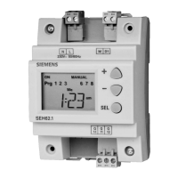
• The SEH62.1 time switch is designed for indoor use
Measures to be taken to avoid radio interference
• Do not install the time switch near strong electromagnetic fields
• Inductive components near the time switch must be fitted with inter-
ference suppressors (RC units or varistors)
• Ensure adequate air circulation to dissipate the heat generated
during operation
• In general, standard cable can be used. If the time switch must be
installed in environments with strong electromagnetic fields,
shielded cable should be used
Mounting choices
The time switch can be mounted as follows:
A On top hat rails.
Type of rail: EN 50 022-35 x 7.5, min. 60 mm long.
B Wall-mounting with 2 screws.
2 fixing holes are provided.
C Flush panel-mounting with standard elements, e.g. 1 top hat rail
100 mm long, 2 hexagonal spacers, washers and screws.
D In protective housing ARG62.22 (when used outside control
panels).
AB C D
5243Z02
The connection terminals must be freely accessible.
Electrical installation
Precautionary measures
• Ensure that local safety regulations are complied with
• Between the connection terminals and the mounting plate or metal
covers, there should be a minimum clearance 8 mm
• The connection terminals must be protected by a plastic cover
• Never open the time switch
• Note the maximum switching capacity of the relay contacts:
AC 240 V, DC 24 V / 6 A resistive, 3 A inductive
Internal diagram
Q14
Q11
N
L
5243G01
D1 M
Q12
L, N AC 230 V mains supply
M, D1 Digital input (momentary contact closure)
Q… Digital output
Commissioning
LCD
Prg 1 2 3 4 5 6 7 8
Su Mo Tu We Th Fr Sa
am
pm
ON OFF AUTO MANUAL
Status line
Program selection
Weekday
Time/setup title line
Countdown
enable
5243 Z01en
Operating elements
The time switch has 3 buttons with the following functions:
SEL
Button for confirming a selected or entered value. This
button also serves as a manual ON/OFF switch for over-
riding the programmed switching sequences
+
-
Buttons for setting and displaying the time of day, week-
day and switching program
Programming
Setting the current time of day, weekday and count-
down timer
What How Display
1 Initialization
Press the + and - buttons simultane-
ously for 5 seconds in normal opera-
tion so that TIME appears flashing
TIME
2
12 / 24-hour
format
Press the SEL button within 1 min-
ute after initialization, then press the
+/- buttons to select the display for-
mat. Confirm with the SEL button
12HR
or
24HR
3
Set the cur-
rent time of
day
After selection of the time format,
press the +/- buttons within 1 minute
to set the current time of day. Con-
firm with the SEL button
E.g.
10:30
4
Set the cur-
rent weekday
After setting the current time of day,
press the +/- buttons within 1 minute
to set the current weekday. Confirm
with the SEL button
Su…Sa
5
Setting the
countdown
timer
After setting the weekday, press the
+/- buttons to select CTDN and con-
firm with the SEL button. Then, set
the timer’s required ON time by
pressing the +/- buttons. Press the
SEL button again so that CTDN
appears again
CTDN
6
Exit the time
or timer set-
ing
When, after setting the weekday (step
no.4) or the timer, TIME or CTDN
appears flashing again, press the +/-
buttons to select EXIT and close with
the SEL button
EXIT
Note: When, in programming mode, no button is pressed for 1
minute, the timer will automatically return to normal opera-
tion.
If the countdown timer is not required, skip step no. 5.
The countdown timer is started by a momentarily closing
contact connected to M - D1. The N.O. contact across
Q11 - Q14 remains closed until the set time has elapsed.
For latest prices and delivery to your door visit MyTub Ltd - www.mytub.co.uk - info@mytub.co.uk 0844 556 1818
 Loading...