Basic Principles of Serial Data Transmission
2.5 Data transfer using the ASCII driver
PtP coupling and configuration of CP 340
48 Manual, 04/2011, A5E00369892-03
● Data can be received via the RS 232C interface as soon as the DSR line is set to ON. If
the CP 340's receive buffer is close to overflow, the CP 340 will not respond.
● An active send job or data receiving operation will be cancelled and an error message
output if DSR changes from ON to OFF. The message "DSR = OFF (automatic use of
V24 signals)" is entered in the diagnostic buffer of the CP 340.
Note
When automatic control of the RS 232C accompanying signals is configured, neither
RTS/CTS data flow control nor RTS and DTR control by means of the V24_SET FC are
possible.
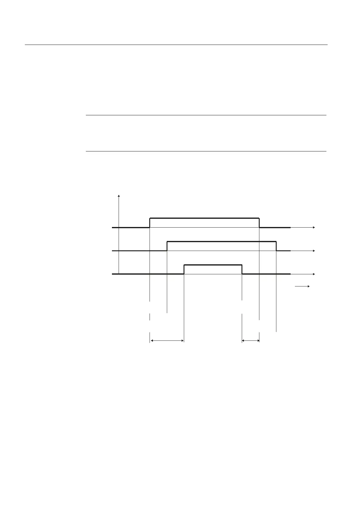
Timing diagram
The figure illustrates the chronological sequence of a send job.
576
2))
21
&76
21
7;'
576 21
&76 21
&76 2))
2))
W
5HTXHVWWRVHQG
3DUWQHUV
3DUWQHUV
'DWDRXWSXWZDLWLQJWLPH
HODSVHGൺ6HQG
7LPHWR
5762))
'DWDRXWSXW
ZDLWLQJWLPH
6HQG
FRPSOHWHG
7LPHWR5762))
HODSVHG
Figure 2-13 Timing diagram for automatic control of RS 232C accompanying signals