Supplements to ET 200SP documentation
2.5 I/O module manuals
Product information on the documentation of the ET 200SP distributed I/O system
Product Information, 02/2021, A5E03799595-BG
49
Manual Digital Output Module DQ 4x24..230VAC/2A ST, Edition 03/2015
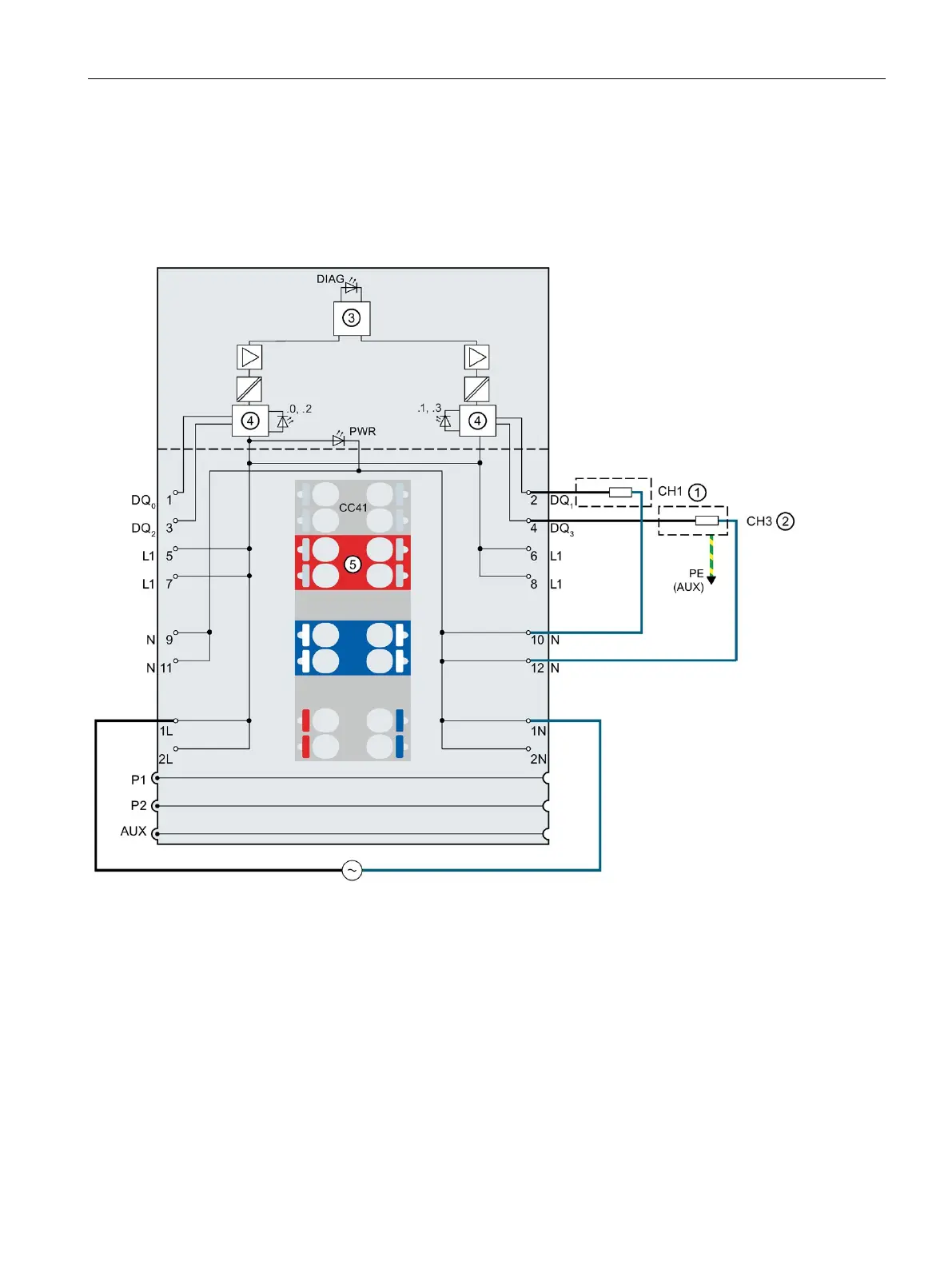
Section 3.1 Wiring and block diagram
The following figure shows the block diagram and an example of the pin assignment of the
digital output module DQ 4x24..230VAC/2A ST on the BaseUnit BU type B1.
Supply voltage 24 V AC to 230 V AC
Neutral conductor supply voltage
Protective conductor connection
Color-coded label CCxx (optional)
Diagnostics LED (red/green)
Channel status LED (green)
P1, P2, AUX Internal self-assembling voltage buses
Connection to left (dark-colored BaseUnit)
Figure 2-2 Wiring and block diagram for 2-wire and 3-wire connection of actuators.

 Loading...


