Supplements to ET 200SP documentation
2.5 I/O module manuals
Product information on the documentation of the ET 200SP distributed I/O system
Product Information, 02/2021, A5E03799595-BG
53
Manual RQ 4x120VDC-230VAC/5A NO MA ST, Edition 12/2015
Section 3.1 Wiring and block diagram
The AUX terminals of the self-assembling voltage bus can be used for the connection of the
protective conductor (PE) or for voltages up to a maximum of 24 V DC.
2.5.2 Analog module device manuals
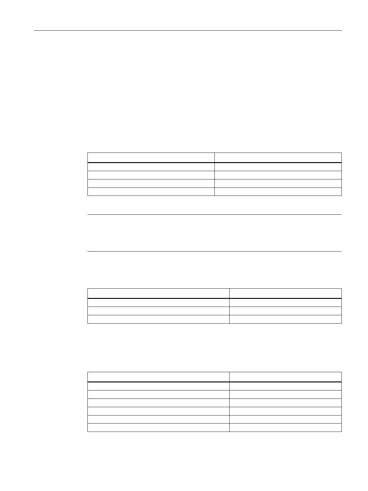
Manuals for analog input modules
AI 4xI 2-wire 4..20mA HART
Section 5.2 "Parameters"
Note
Note that the settings in the "Interference frequency suppression" parameter have a direct
effect on the cycle time of the
module. The analog value is therefore also affected by
additionally set filtering via the "Smoothing" parameter.
Manuals for analog input modules
AI 4xRTD/TC 2/3/4-wire HF (6ES7134-6JD00-0CA1)
AI 8xRTD/TC 2-wire HF (6ES7134-6JF00-0CA1)
AI 4xTC HS (6ES7134-6JD00-0DA1)
For user calibration with a calibration device, deactivate the "Wire-break check" parameter or
function.
Manuals for analog input modules
AI 8xI 2/4-wire Basic (6ES7134-6GF00-0AA1)
AI 4xU/I 2-wire ST (6ES7134-6HD01-0BA1)
AI 2xI 2/4-wire ST (6ES7134-6GB00-0BA1)
AI 2xU/I 2/4-wire HF (6ES7134-6HB00-0CA1)
AI 2xU/I 2-, 4-wire HS (6ES7134-6HB00-0DA1)
AI 4xI 2/4-wire ST (6ES7134-6GD01-0BA1)

 Loading...


