Contact Assignment
F1 Fault contact 1
F2 Fault contact 2
Signaling faults
● The signaling of errors by the signaling contact is synchronized with the fault LED "F", see
section ""F" LED (Page 31)".
All errors that the fault LED "F" indicates (freely configurable) are also signaled by the
signaling contact.
● If an internal fault occurs, the fault LED "F" lights up and the signaling contact opens.
● If you connect a communications node to an unmonitored port or disconnect it, this does
not cause an error message.
● The signaling contact remains open until one of the following events occurs:
– The problem is eliminated.
– The current status is entered in the fault mask as the new desired status.
5.5 Serial interface
Information on the serial interface
● Via the serial interface on the device (RJ-11 jack), you can access the Command Line
Interface of the device directly via an RS-232 (115200 8N1) connection without assigning
an IP address.
● Access to the device is possible independent of the Ethernet ports.
● To connect the serial interface to a PC, you require a cable with an RJ-11 plug and 9-pin
D-sub female connector. The connecting cable for the serial interface can be ordered as
an accessory.
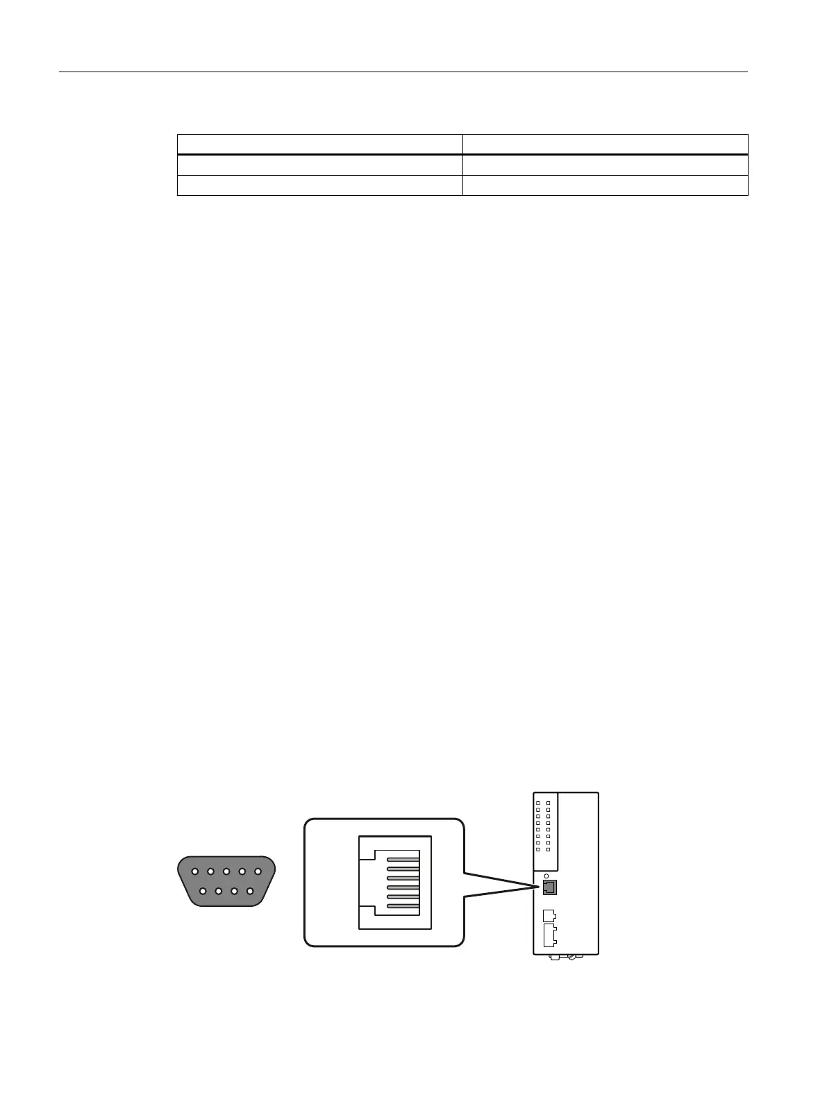
Position and assignment
Figure 5-3 Position and pin assignment of the serial interface (RJ-11 jack), based for example on the
XC-200 with 8 ports as well as the pin assignment of the D-sub socket.
Connecting up
5.5 Serial interface
SCALANCE XC-200
54 Operating Instructions, 12/2017, C79000-G8976-C442-03
 Loading...