Readers
5.4 SIMATIC RF680R
SIMATIC RF600
System Manual, 11/2018, J31069-D0171-U001-A21-7618
147
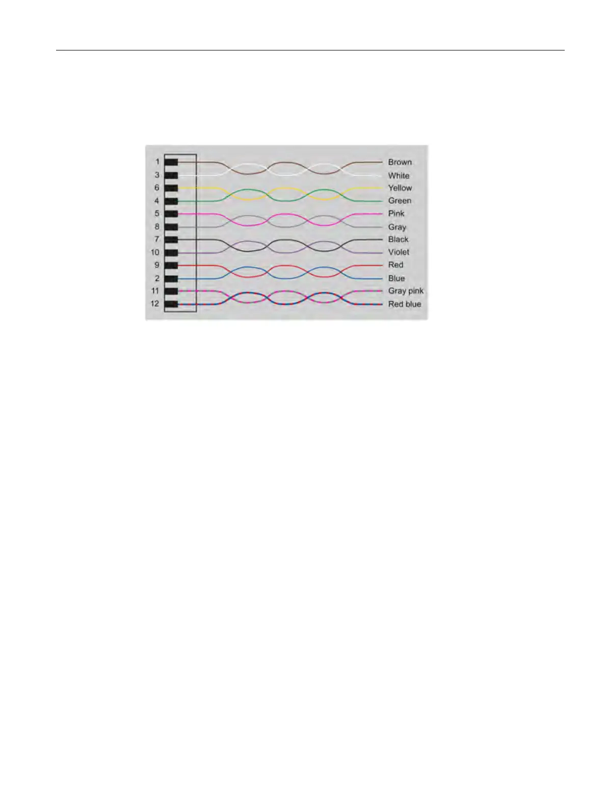
Color scheme of the DI/DQ standard cable with M12 connector
The following figure shows the color scheme of the DI/DQ standard cable from Siemens
(6GT2891-0CH50). You can use the color scheme to assign the wire colors to the pins.
Figure 5-19 Wiring diagram: M12 connector
5.4.1.4 Switching scheme for the DI/DQ interface
Connection possibilities
You can connect the reader in different ways. In general, the outputs and inputs should be
connected as follows:
Output (DO 0 ... 3)
● Each output is rated for 0.5 A current and is electronically protected.
● 4 digital outputs can be operated simultaneously each with up to 0.5 A (up to 1 A in total).
With a total current > 1 A, you need to use an external power supply.
● The outputs are optically isolated through optocouplers.
input (DI 0 ... 3)
● The inputs are optically isolated through optocouplers.
● Level
– Low: 0 ... 7 V
– High: 15 ... 24 V
● Sampling rate
< 20 ms