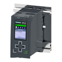
Block diagram
The following figure shows the block diagram of the CPU1517H‑3PN.
/
0
;3
31
;35
;3
31
;35
;3
31
;3
+6<1&
;3
;3
56(507
+6<1&
;3
;3
① SIMATIC memory card (X50) PN X1 P2R PROFINET interface X1port2
② Display PN X2 P1 PROFINET interface X2 port1
③ Mode selector RUN/STOP/MRES HSYNC X3P1 H-Sync interface X3 port1
④ Electronics HSYNC X4P1 H-Sync interface X4 port1
⑤ PROFINET 2-port switch L+ 24VDC supply voltage
⑥ Synchronization interface M Ground
⑦ Backplane bus connection
(connection to backplane bus not configur
able)
R/S RUN/STOP LED (yellow/green)
⑧ Internal supply voltage ER ERROR LED (red)
⑨ Supply of the 24VDC supply voltage (X80) MT MAINT LED (yellow)
PNX1P1R PROFINET interface X1port 1 X1P1, X1P2,
X2P1, X3P1,
X4P1
LED Link TX/RX
Figure 4-3Block diagram of the CPU1517H‑3PN
29
Connecting
4.1 Terminal assignment
CPU1517H-3PN (6ES7517-3HP00-0AB0)
Equipment Manual, 11/2022, A5E42011886-AD

 Loading...


