4 Configuration and Project Engineering
4.1 Creating the project configuration
SINAMICS G120 as a Speed Axis on the S7-1500
V1.0a, Entry ID: 78788716
Copyright Siemens AG 2013 All rights reserved
No. Action Picture
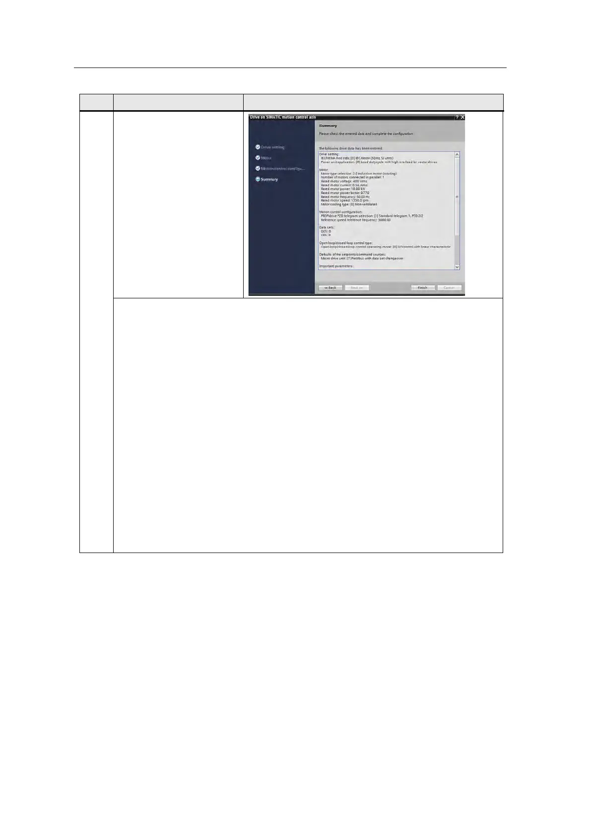
16. The wizard is self-
explanatory.
Enter your motor data here.
Make sure that the same
telegram as in the previous
step is selected at this point.
A summary is displayed
before you complete the
parameterization with
“Finish”. This summary can
be backed up using copy and
paste.
The parameterization in the application example is shown below:
Drive setting:
IEC/NEMA mot stds: [0] IEC-Motor (50 Hz, SI units)
Power unit application: [0] Load duty cycle with high overload for vector drives
Motor:
Motor type selection: [1] Induction motor (rotating)
Number of motors connected in parallel: 1
Rated motor voltage: 400 Vrms
Rated motor current: 0.56 Arms
Rated motor power: 18.00 kW
Rated motor power factor: 0.770
Rated motor frequency: 50.00 Hz
Rated motor speed: 1350.0 rpm
Motor cooling type: [0] Non-ventilated
Motion control configuration:
PROFIdrive PZD telegram selection: [1] Standard telegram 1, PZD-2/2
Reference speed reference frequency: 3000.00
Data sets:
DDS: 0
CDS: 0
Open-loop/closed-loop control type:
Open-loop/closed-loop control operating mode: [0] U/f control with linear characteristic
Defaults of the setpoints/command sources:
Macro drive unit: [7] Fieldbus with data set changeover
Important parameters:
Current limit: 0.84 Arms
Minimum speed: 0.000 rpm
Maximum speed: 1500.000 rpm
Ramp-function generator ramp-up time: 0.000 s
Ramp-function generator ramp-down time: 0.000 s
OFF3 ramp-down time: 0.000 s
Drive functions:
Motor data identification and rotating measurement: [0] Inhibited
Automatic calculation motor/control parameters: [1] Complete calculation
 Loading...


