Do you have a question about the Siemens SIMATIC S7-200 CPU226 and is the answer not in the manual?
Provides an example of communication settings in GP-Pro EX for the Ethernet Gateway.
Details communication setup items configurable within GP-Pro EX software.
Explains how to configure setup items for the display directly in offline mode.
Lists the range of supported device addresses for the S7-200 series.
Lists the range of supported device addresses for the S7-300/400 series.
Defines the device and address codes used for the S7-200 series.
Defines the device and address codes used for the S7-300/400 series.
This document outlines the connection and configuration of an Ethernet Gateway for SIMATIC MPI/PROFIBUS Driver, enabling communication between a display unit and Siemens AG external devices (PLCs). It details the necessary steps for system setup, external device selection, communication settings, and troubleshooting.
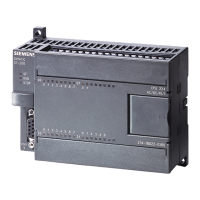
The primary function of this device is to act as an Ethernet gateway, facilitating communication between a display unit and Siemens SIMATIC S7-200, S7-300, and S7-400 series PLCs via MPI/PROFIBUS. This allows for data exchange and control between the display and the external device, enabling human-machine interface (HMI) functionalities. The gateway supports various CPU types within these SIMATIC series, including CPU214, CPU215, CPU216, CPU221, CPU222, CPU224, CPU226 for S7-200, and a range of CPU3xx and CPU4xx models for S7-300 and S7-400 respectively. Connection to S7-200 series PLCs is typically via Port 0/1 on the CPU unit, while S7-300 and S7-400 series PLCs connect via their MPI ports. All connections utilize Ethernet (TCP) as the communication method.
The gateway supports flexible connection configurations, including 1:1, 1:n, and n:m connections. In a 1:1 connection, a single display unit connects to a single external device via an adapter. For 1:n connections, a single display unit can connect to a maximum of 12 external devices, either directly through an adapter or by using a HUB and an adapter. The n:m connection allows multiple display units to connect to multiple external devices. The maximum number of display units in an n:m configuration can be up to 12, or 7 if a HUB is used, while the maximum number of external devices remains 12. A key constraint is that only one adapter can be connected to one display unit.
Configuration of the gateway is primarily done through the GP-Pro EX software or in the display's offline mode. The "External Device Selection" process involves specifying the number of devices/PLCs to connect (from 1 to 4), selecting "Siemens AG" as the manufacturer, and choosing "Ethernet Gateway for SIMATIC MPI/PROFIBUS" as the series. The display port to be connected to the external device is "Ethernet (TCP)". An important feature is the "Use System Area" option, which synchronizes the system data area of the display and the memory of the external device. This synchronization enables the external device's ladder program to switch displays or show windows on the display, enhancing interactive control.
Communication settings are crucial for establishing a stable connection. These settings include the Port No. (default 1024, with an auto-setting option), Timeout (1 to 127 seconds), Retry attempts (0 to 255), and Wait To Send time (0 to 255 milliseconds). The Gateway/Module Setup requires inputting the IP Address of the gateway/module, which can be searched for in the local area network. The Port No. for the gateway/module is also displayed (default 7777). MPI/PROFIBUS Network Configuration settings include Speed (e.g., 187500), Local Node (the node number of the display in the MPI/PROFIBUS network), and Highest Node Number (the maximum node number in the network, typically 31).
Device-specific settings are accessed through the "Individual Device Settings" dialog. Here, the PLC Type is selected, with options for S7-300/400 Series (English or German Device Names) and S7-200 Series (English or German Device Names). The Target Node number (0 to 126) for the external device must be set, ensuring it does not exceed the "Highest Node Number" defined in the communication settings.
External device settings are configured via a web browser, accessing the adapter's home page (e.g., http://<ip-address>). The default IP address for the adapter is 192.168.4.49. Access to the configuration page requires a username (NETLink PRO) and password (default 'admin'). Configurable items include Device name (up to 20 alphanumeric characters), Static IP address, Static subnet mask, DHCP ON/OFF, DHCP Timeout (30 to 65500 seconds), Web interface ON/OFF, RFC1006 parameters (not needed for GP-Pro EX), and New passwords (up to eight characters). After saving, the adapter restarts to apply the new configuration.
The gateway supports a range of device addresses for SIMATIC S7-200 and S7-300/400 series PLCs, including Variables (VW), Input (I/E, IW/EW), Output (Q/A, QW/AW), Internal Marker (M, MW), Timer (T), and Counter (C/Z). For S7-300/400, Data Block (DB, DBW) addresses are also supported. Specific considerations apply to writing to certain addresses, such as IW0 to IW2 for S7-200, which may be reserved for onboard I/O, and QW/Q devices, which can only be written to when the external device is in RUN mode. Timers and counters are generally write-disabled.
The manual provides guidance on error messages displayed on the screen, which follow a format of "No. : Device Name: Error Message (Error Occurrence Area)". Each error message includes an error number, the name of the external device where the error occurred, a description of the error, and an error occurrence area that displays the IP address, device address, or received error codes. For example, "RHAA035: PLC1: Error has been responded for device write command (Error Code: 2 [02H])" indicates an error during a device write command.
For detailed information on received error codes from the external device, users are directed to consult the external device's manual. For common error messages related to the driver and display-related errors, users are advised to refer to the "Maintenance/Troubleshooting Guide". The manual also references the "GP-Pro EX Reference Manual" for information on system data areas, LS Area (Direct Access Method Area), and changing the device/PLC at runtime (indirect device). Precautions regarding manual notation for icons and symbols are also mentioned. These resources are essential for diagnosing and resolving issues during operation and maintenance.
| Number of I/O | 24 inputs / 16 outputs |
|---|---|
| Communication Ports | 1 x RS-485 |
| Operating Voltage | 24 VDC |
| Digital Inputs | 24 |
| Digital Outputs | 16 |
| Temperature Range | 0°C to 55°C |
| Dimensions | 80 x 62 mm |