5 MODBUS RTU Protocol communication
CP340/CP341/CP440/CP441 Communication and Programming
Entry-ID: 88867653, V1.0, 02/2014
Siemens AG 2014 All rights reserved
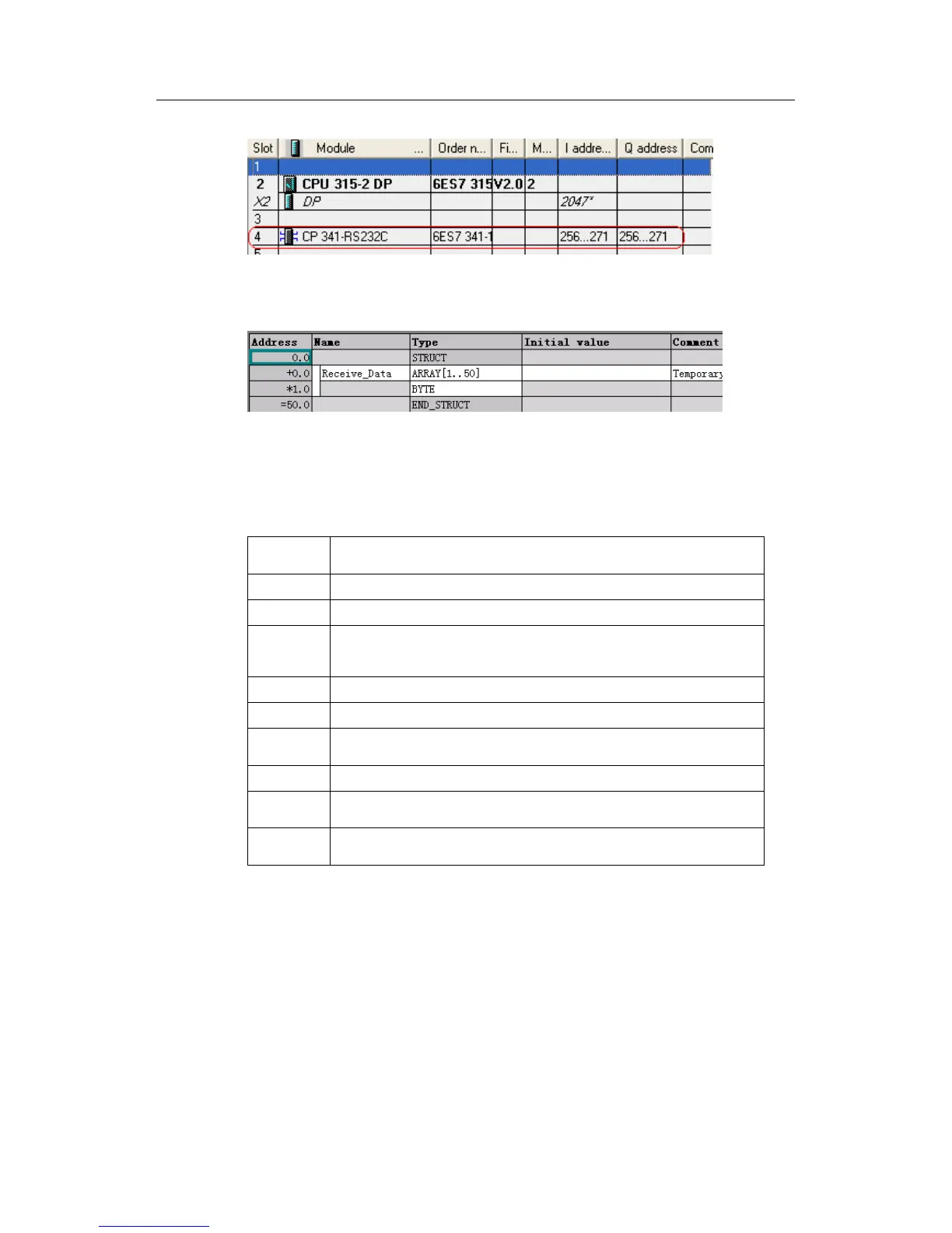
Fig. 91: Logic address of CP341
5. Create receive data block DB2
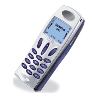
Fig. 92:Receive data block DB2
6. Invoke receive function block
The FB7 P_RCV_RK parameter setting may be seen in the table below:
Start logic address in hardware configuration, which is 256 in this
example
Send Data block number, which is 2(DB2) in this example
Start address of Send Data, which is 0(DB2.DBB0) in this example
Length of receive data, which is MW4 in this example.This value is not
0 only in the current cycle when data are received. The length of
received data may be determined by checking the MW8 value.
Enable receive bit, which is M0.3 in this example.
Cancel communication, which is not applicable in this example
Receive complete bit, which is TRUE if Receive completes and has no
error
error bit, TRUE indicating that it has an error
Status word, ID error code. See Modbus Master Manual - Chapter 7 for
related description.
Not applicable in this example.
Table 14: Parameter definition of FB7 P_RCV_RK