2.3 Cantilever and axial force diagrams
1PH7/2-112
Siemens AG, 2004. All rights reserved
Induction Motors, 1PH7 (APH7S) – 05.04 Edition
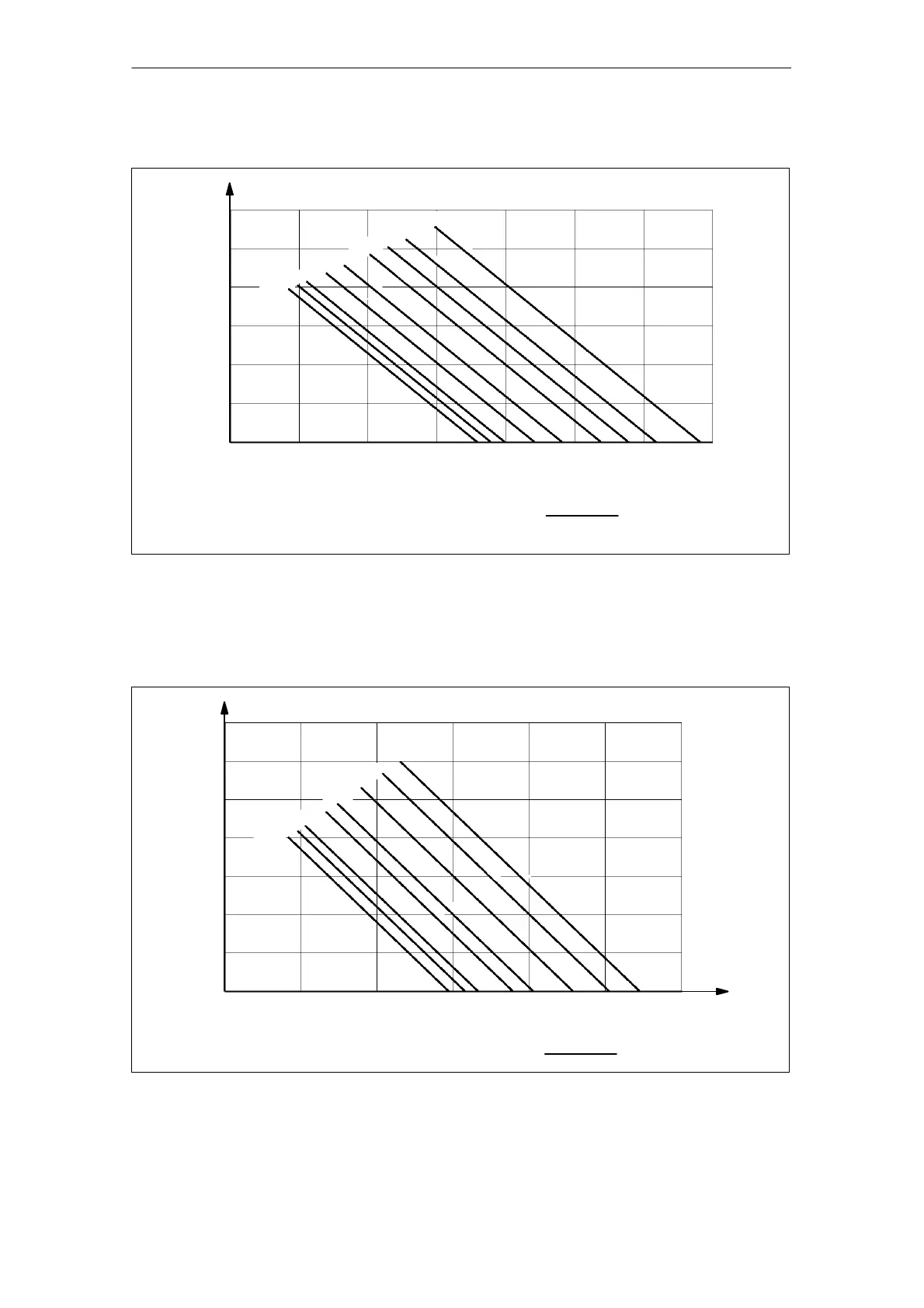
SH 100, permissible axial force at the shaft end
n = 1000 RPM
2000
3000
4000
5000
6000
7000
8000
9000
Bearings, DE: 6308 F
C
= 400 N
Bearings, NDE: 6208
L
h
= 12000 h
0.5 1.512 10
3
F
A
[N]
3000
2000
1000
F
QAS
[N]
F
C
= Alignment force
Fig. 2-72 Axial force diagram at the shaft end, shaft height 100
When determining the axial force, refer to the Planning Guide, “General Section”.
SH 132, permissible axial force at the shaft end
Bearings, DE: 6310 F
C
= 600 N
Bearings, NDE: 6210
L
h
= 12000 h
1234 10
3
F
A
[N]
3000
2000
1000
F
QAS
[N]
n = 1000 RPM
2000
3000
4000
5000
6000
7000
8000
F
C
= Alignment force
Fig. 2-73 Axial force diagram at the shaft end, shaft height 132
Technical Data and Characteristics