Motor Description
1.7 Electrical connections
1PH7/1-23
Siemens AG, 2004. All rights reserved
Induction Motors, 1PH7 (APH7S) – 05.04 Edition
1.7 Electrical connections
1.7.1 Connecting-up induction motors
Note
The motors can be fed from a DC link voltage of up to 700 V DC. For shaft heights
180 and 225, the appropriate version must be selected.
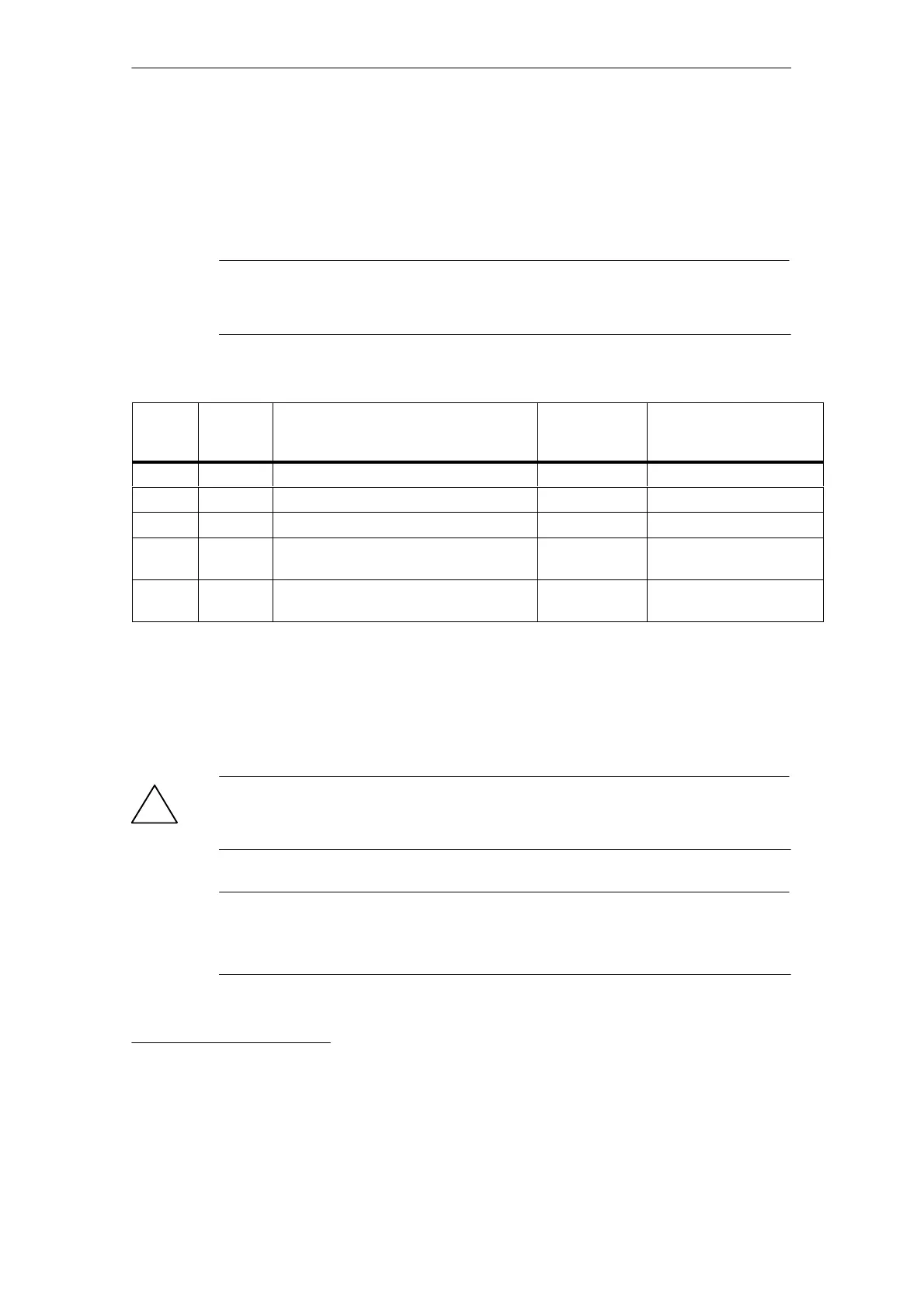
Table 1-7 Overview, connection system for 1PH7 motors
SH
Number
of main
terminals
Max. cross-section that can be
connected
Terminal strip
for temperature
sensor
PE connection size/
cable lug width
100 6 x M5 25 mm
2
3 terminals M5/9 mm
132 6 x M6 35 mm
2
with cable lug connection 3 terminals M6/15 mm
160 6 x M6 50 mm
2
with cable lug connection 3 terminals M6/18 mm
2)
180 3 x M12 2 x 50 mm
2
with cable lug connection 4 terminals Without cable lug using a
terminal clamp
1)
225 3 x M12 2 x 50 mm
2
with cable lug connection 4 terminals Without cable lug using a
terminal clamp
1)
Power cable
The power cables for 1PH motors are selected according to the rated motor cur-
rent I
N
at +40 °C according to Table 1-8.
!
Caution
Carefully observe the current which the motor draws for your particular application!
Adequately dimension the connecting cables according to IEC 60204-1.
Note
The cables are available in a UL version or for higher mechanical requirements.
Technical data, refer to Catalog, Chapter “Connection System”.
1) Cable cross-section, corresponding to the line conductor cross-section
2) Cable lug acc. to DIN 46234