Motor Components
3.3 Gearboxes
1PH7/3-126
Siemens AG, 2004. All rights reserved
Induction Motors, 1PH7 (APH7S) – 05.04 Edition
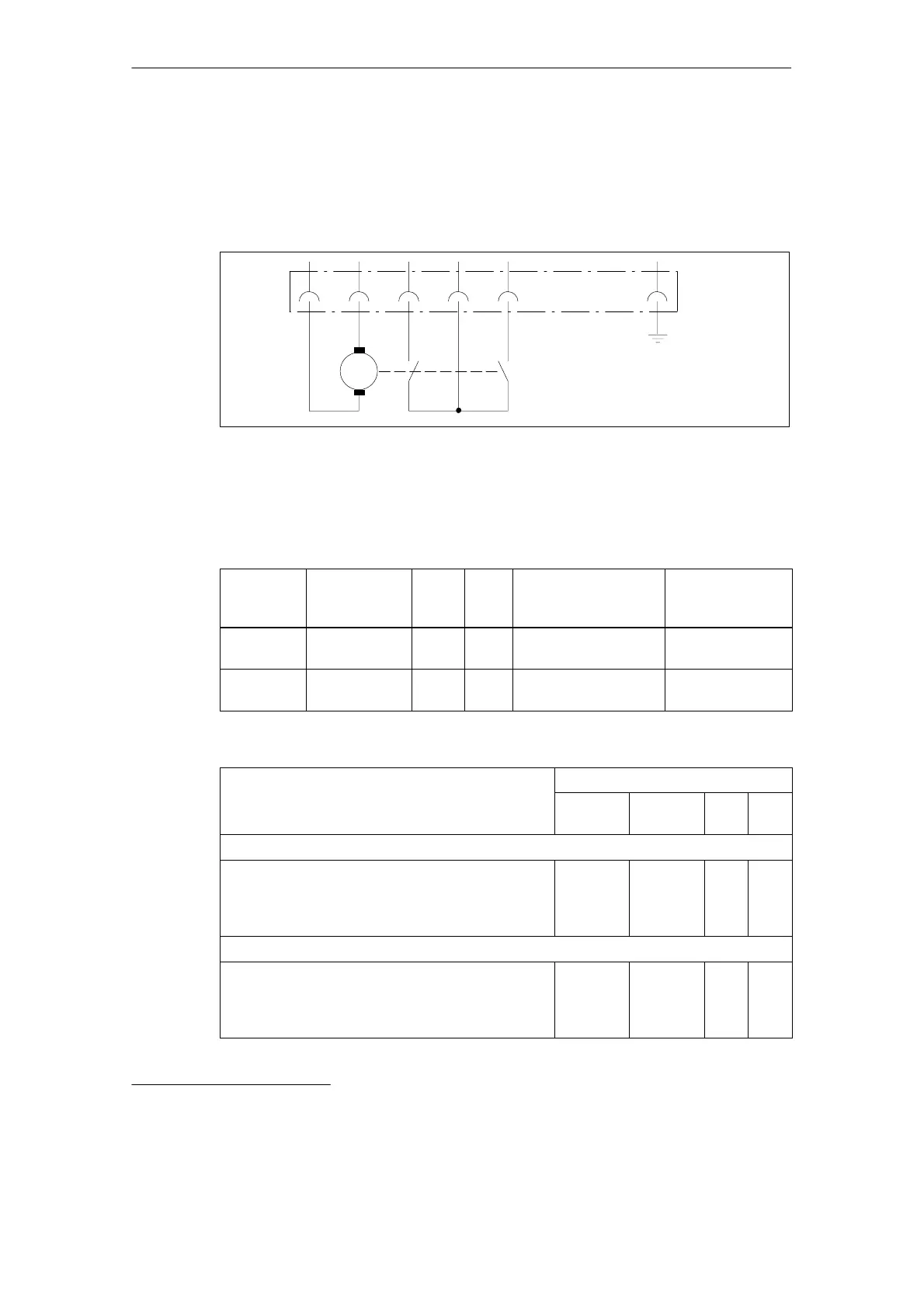
3.3.4 Electrical connections
Power supply for the selector unit: 24 V DC 10 %
The mechanical selector unit requires a separate supply.
PE
M
–
S1 S2
56432
Fig. 3-5 Circuit diagram
Connector (incl. in the scope of supply): Manufacturer, Harting; 7-pin + PE, type
HAN 7D
Table 3-4 Explanation of the connections
Connector
contact
No.
Number and
designation
In-
put
Out-
put
Voltage Current
2 and 3 1 selector unit 0 – 24 V DC I
max
= 5 A
(inrush current)
4 and 6 2 limit
switches
0 0 24 V DC
U
max
=42 V DC
I
max
= 5 A
Table 3-5 Control sequence when selecting the gearbox stage
Gearbox stage selection
Connector contact No.
2 3 4/5
(S1)
5/6
(S2)
When changing the ratio from stage i
2
to i
1
a Initial setting (f)
b Selection sequence
c Mechanical selection
carried-out up to endstop
1)
+24 V DC 0 V 0
0
L
L
0
0
When changing the ratio from stage i
1
to i
2
d Initial setting (c)
e Selection sequence
f Mechanical selection
carried-out up to endstop
1)
0 V +24 V DC L
0
0
0
0
L
L Contact closed 0 Contact open
1) A limit switch (S1 or S2) sends a signal to the control after selection to switch out the selector unit.