Motor Description
1.4 Order number
1PH7/1-17
Siemens AG, 2004. All rights reserved
Induction Motors, 1PH7 (APH7S) – 05.04 Edition
1.4 Order number
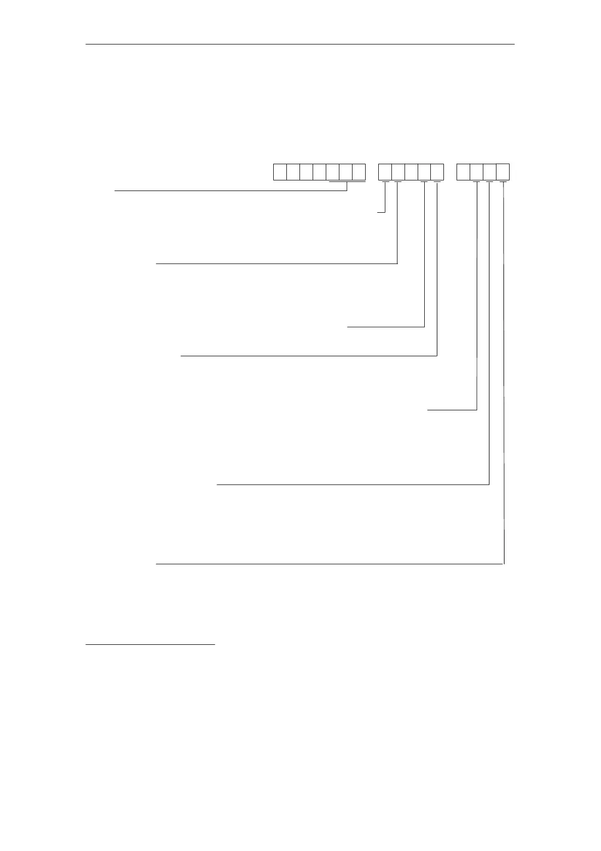
Motor type, design features and additional data are coded in the Order designation.
SH 100 to 160 standard version
. . .–..
Encoder system
E = absolute value encoder (EnDat 2048 S/R)
N = incremental encoder sin/cos 1 Vpp (without C and D tracks)
M = incremental encoder sin/cos 1 Vpp (with C and D tracks)
–0.
Size
1 P H 7 . ... .
Cable entry direction (top of the terminal box, when view the DE)
0 = from the right, 2 = from NDE, 3 = from the left
Separately-driven fan, 3-ph. 400 V AC/50 Hz or 3-ph. 480 V AC/60 Hz
2 = with separately-driven fan, PG cable entry
7 = with separately-driven fan, metric cable entry according to EN 50262
Type of construction
0 = IM B3, IM V5, IM V6
2 = IM B5, IM V1, IM V3 (only for SH 100 and SH 132)
3 = IM B35, IM V5, IM V36
Drive type Vibration severity level Shaft and flange accuracy
B = coupling and belt R R
C = coupling and belt S R
D = coupling and belt SR R
K = coupling and belt N N (only for a mounted brake)
L = increased maximum speed
2)
SR R
Air flow direction Shaft end
A = DE –> NDE with key, half-key balancing
B = NDE –> DE with key, half-key balancing
C = DE –> NDE with key, full key balancing
D = NDE –> DE with key, full-key balancing
J = DE –> NDE smooth
K = NDE –> DE smooth (no keyway)
Paint finish
0 = without
2 = without, oiltight flange with radial shaft sealing ring
3 = anthracite, standard paint finish
5 = anthracite, standard paint finish, oiltight flange with radial shaft sealing ring
6 = anthracite, special paint finish
8 = anthracite, special paint finish, oiltight flange with radial shaft sealing ring
1) Not for every shaft height
2) Version for increased maximum speed only in conjunction with vibration severity level SR.
Option not possible for: – prepared for mounting a ZF gearbox
– shaft seal