2.3 Cantilever and axial force diagrams
1PH7/2-114
Siemens AG, 2004. All rights reserved
Induction Motors, 1PH7 (APH7S) – 05.04 Edition
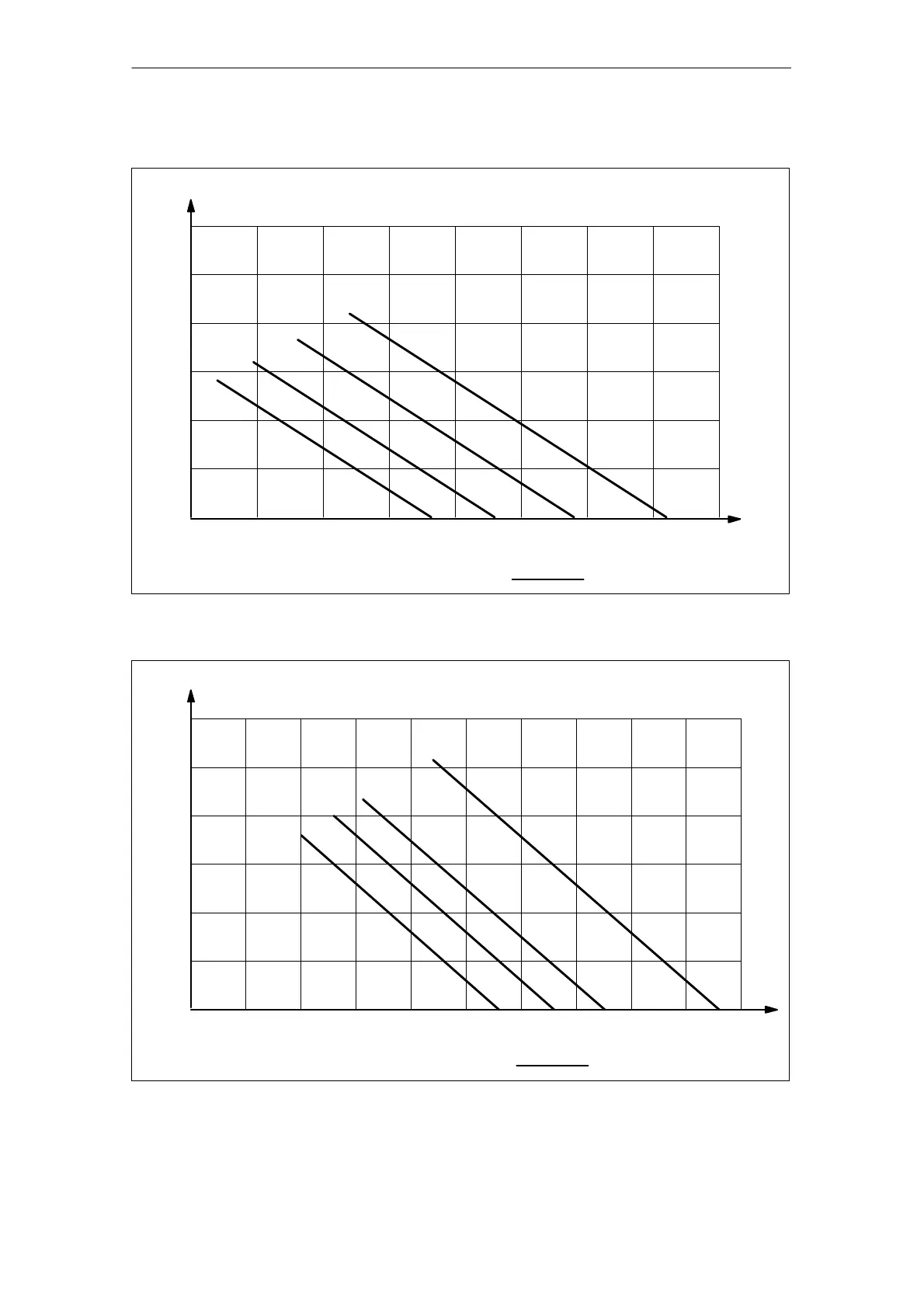
SH 100, permissible axial force at the shaft end for increased max. speed
n = 1000 RPM
5000
12000
9000
Bearings, DE: 6208 F
C
= 400 N
Bearings, NDE: 6208
L
h
= 8000 h
0.5 1.51 2.5 10
3
F
A
[N]
3000
2000
1000
F
QAS
[N]
F
C
= Alignment force
2
Fig. 2-75 Axial force diagram at the shaft end, shaft height 100 (increased max. speed)
SH 132, permissible axial force at the shaft end for increased max. speed
n = 1000 RPM
4000
10000
6000
Bearings, DE: 6210 F
C
= 400 N
Bearings, NDE: 6210
L
h
= 8000 h
0.5 1.51
3 10
3
F
A
[N]
3000
2000
1000
F
QAS
[N]
F
C
= Alignment force
2
2.5
Fig. 2-76 Axial force diagram at the shaft end, shaft height 132 (increased max. speed)
Technical Data and Characteristics