Motor Description
1.10 Mounting
1PH7/1-33
Siemens AG, 2004. All rights reserved
Induction Motors, 1PH7 (APH7S) – 05.04 Edition
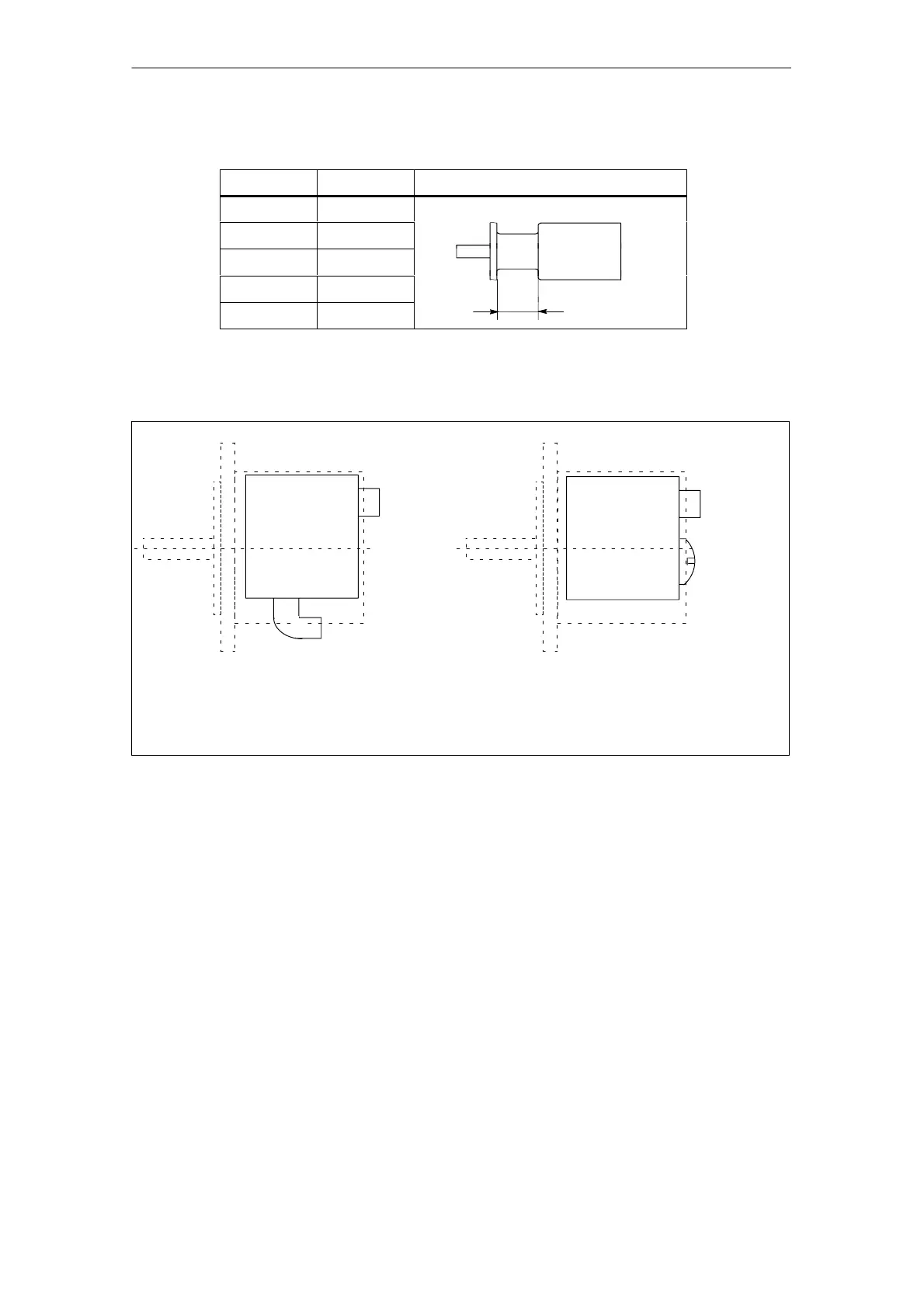
Table 1-16 Flange mounting with studs and nuts
Shaft height
M1 [mm]
100 44
132 50
160 65
1PH7
180 36
225 40
M1
Cable outlet NDE
Signal
connector
Power connection
Power
connection
(angled element is included in the scope of
supply)
SH 180 to 225: Via terminal box, depending on the version ordered
Terminal box
Terminal box
Signal
connector
SH 100 SH 132 to 160
Fig. 1-6 Cable outlet
Mounting information and instructions
The following mounting instructions must be carefully observed:
For high-speed machines, we recommend that the complete unit is dynamically
balanced after couplings or belt pulleys have been mounted.
Use suitable equipment when mounting drive elements. Use the thread at the
shaft end.
Do not apply any blows or axial pressure to the shaft end.
Especially for high-speed motors with flange mounting, it is important that the
mounting is stiff in order to locate any resonant frequency as high as possible
so that it remains above the maximum rotational frequency.