2.3 Cantilever and axial force diagrams
1PH7/2-99
Siemens AG, 2004. All rights reserved
Induction Motors, 1PH7 (APH7S) – 05.04 Edition
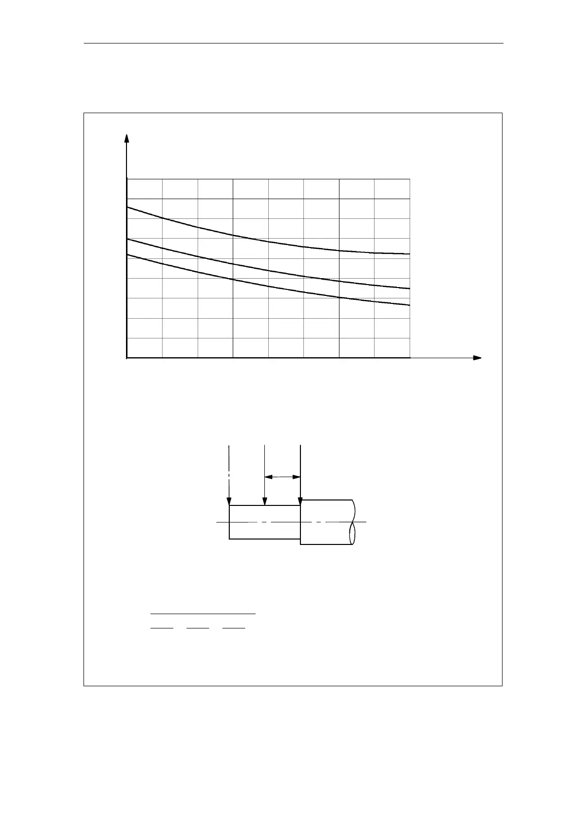
SH 100, permissible cantilever forces for a standard bearing design
123456789 10
3
n [RPM]
L
h1
8000 h
3000
2000
1000
F
QAS
[N]
Bearings, DE: 6308
Bearings, NDE: 6208
Estimated bearing lifetime under different operating conditions (F
QAS
; n)
q = Duration [%] under
constant conditions
L
h
tot
=
100
q
1
L
h1
+
q
2
L
h2
+
q
3
L
h3
F
1QAS
F
QAS
F
2QAS
F
1QAS
= 0.9 F
QAS
F
2QAS
= 1.1 F
QAS
x = 40 mm
x
L
h2
12000 h
L
h3
16000 h
Fig. 2-60 Cantilever force diagram, shaft height 100 for standard bearing designs
Technical Data and Characteristics