VS
07.94
1-101
Siemens AG 1997 All Rights reserved
SIMODRIVE 611A Installation and Start–Up Guide/IAA/–04.97 Edition
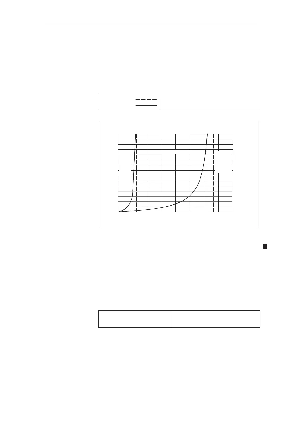
Setting the adaptation range (generally not required)
The adaptation range can be set using the following resistors:
R40 User–friendly interface
R543 Standard interface 1st axis (from Order No. 6SN1118–0AD11–0AA1)
R544 Standard interface 2nd axis (from Order No. 6SN1118–0AE11–0AA1)
Rj= open
Rj= inserted
Maximum adaptation range (as supplied)
Adapt. reduced acc. to the following diagram
150
130
110
90
70
50
30
10
0
0 50 100 150 200 250 300 350 400
R40 in k
n
x
in mV
Adap
_
ta-
tion
fully
eff_
ec-
tive
Transition range
Adap–
tation
inef-
fect–
ive
Fig. 2-8 Adaptation range
n
x
= jn
setp.1
+ n
act.
j
I component limiting of the speed controller
R52 User–friendly interface
R547 Standard interface 1st axis (from Order No. 6SN1118–0AD11–0AA1)
R550 Standard interface 2nd axis (from Order No. 6SN1118–0AE11–0AA1)
R52 = open
R52 =
0 Ω
I component fully effective
(as supplied)
I component ineffective
R52 can be between 100 kΩ and 2 MΩ to limit the speed controller I compo-
nent, e. g. for slipstick effects.
Feed modules (VS)
04.972.6 Setting the adaptation range (generally not required)