VS
07.94
1-124
Siemens AG 1997 All Rights reserved
SIMODRIVE 611A Installation and Start–Up Guide/IAA/–04.97 Edition
Maintenance and diagnostics
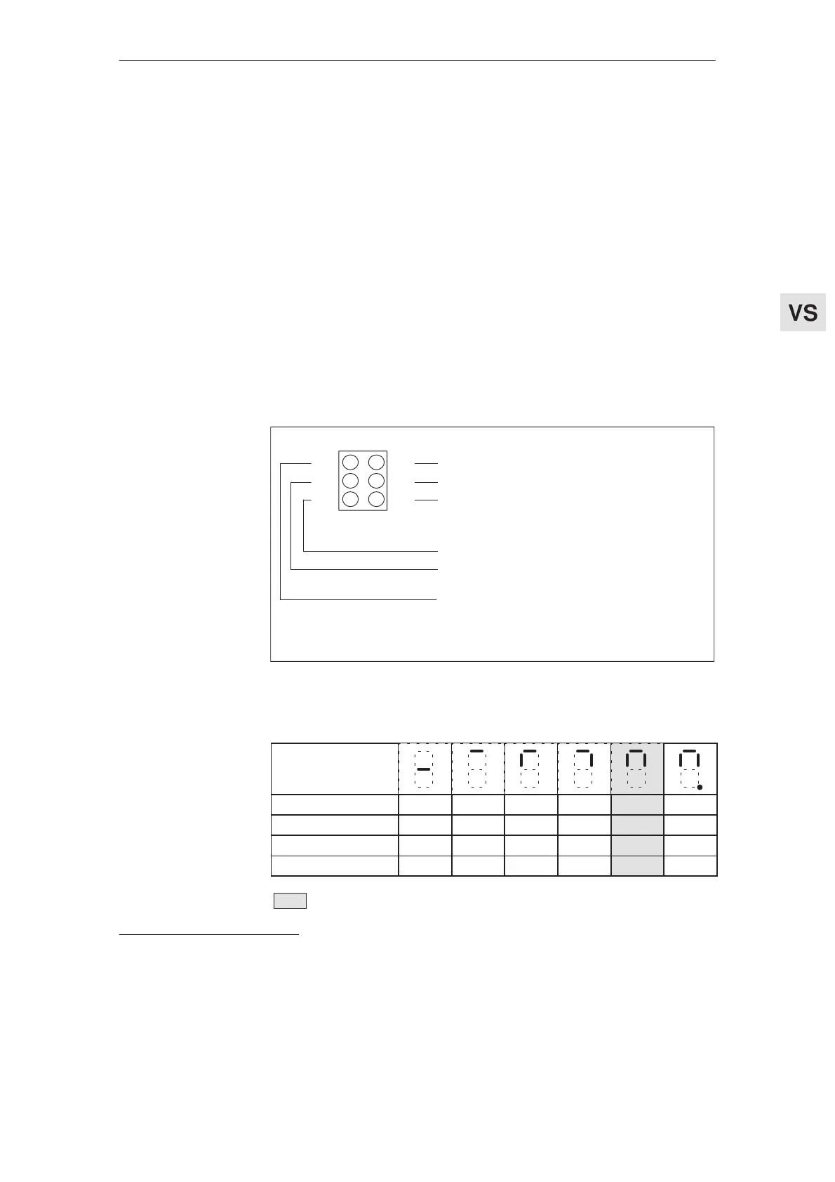
Test sockets and display elements of the feed modules
User–friendly interface
R
NZ
T
X
M
W
Speed setpoint (output)
Current setpoint (output)
Supplementary speed setpoint / supplementary
current setpoint
2)
(input)
Reference ground (output)
Current actual value 10 V, corresponds to the set
I
max
(output)
1)
Speed actual value10 V at rated speed
(1FT503V/4V–0AF71: 11 V) (output)
All outputs have a 1 kWoutput impedance
Fig. 8-1
Par. board inserted No Yes Yes Yes Yes Yes
Pulse enable 663 – No No Yes Yes Yes
Controller enable 65 – No Yes No Yes Yes
Current–controlled No No No No No Yes
Speed–controlled operation (standard operation)
1)
Setting value I
max
refer to p. 1-84, "Current actual value normalization".
2)
Depending on the operating mode, speed–/current controlled
Test sockets
Operating display
Feed modules (VS)
03.96
8.1.1 User-friendl
y interface