VS
07.94
1-110
Siemens AG 1997 All Rights reserved
SIMODRIVE 611A Installation and Start–Up Guide/IAA/–04.97 Edition
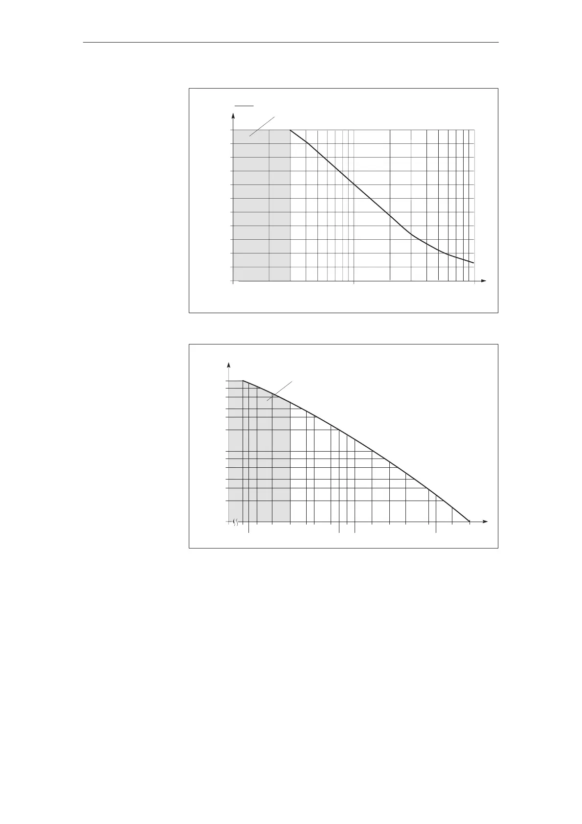
R9 [kΩ]
I
cont.
I
rated
100
90
80
70
60
50
40
30
20
10
10.0 100.0
0
110
1000.0
Illegal area
[%]
Fig. 3-6 Response threshold I
2
t monitoring as a function R9
1.0
0.8
0.6
0.4
0.3
0.2
0.1
0.08
0.06
0.04
0.03
0.02
0.01
5
5.6
6.810 15222739
47
56
68
100
150220390
470
6801000
I
weight
compensation
/I
max
R46 and
R48 [k]
Illegal area
Fig. 3-7 Supplementary current setpoint for electronic weight equalization
Inverter clock frequency PWM
If noise problems occur (the motor makes a whistling sound), the PWM inverter
clock frequency can be adapted by mounting R369 on the basic board.
In this case, it must be observed that the available current (I
n
, I
max
) is redu-
ced when the clock frequency is increased. (refer to Pj Section 4.1)
The I2t limiting is designed for a pulse frequency set in the factory to 3.3 kHz
and a max. ambient temperature of 40
C. When this value is exceeded (pulse
frequency and/or ambient temperature), the response threshold must be adap-
ted (refer to Fig. 3-2).
The characteristic is valid according to Fig. 3-1.
J
Feed modules (VS)
04.973.2 Setting elements with user–friendly interface