11
12
7
6
8
4
3
1
2
5
9
10
Jumpers
Dummy Plug
If the Motor is
disconnected,
the Module
will not fault
if this plug
is installed
- - - - - - - - - - - -
6FX2003-1CF12
- - - - - - - - - - - - - - -
611-A AC Servo
Feed Module
1 ( U )
2 ( V )
6 ( W )
5 ( BR2 )
4 ( BR )
U2
V2
W2
( - )
( +
)
Wiring of Motor to Drive F/B Cable
Tacho, Rotor Position & Thermistor
( suggested Wire Size AWG 22 or 24 )
11
12
7
6
8
4
3
1
2
5
9
10
6FX2003-0CE12
( Motor End )
8
15
7
14
1
9
4
6
13
5
2
11
12
6FC9348-7AT
( Drive End )
NOTE: Motor to Drive connections
must be exactly as shown !
Connections for Optional (G45) Motor Mounted Brake
[24 VDC, + / - 10% - Current range 0.4 to 3.25 Amps
dependent on Motor / Brake size].
If not used, all three (3) wires should be connected to
ground.
Tacho R
Tacho S
Tacho T
Tacho M
P15(RPG)
RPD R
RPD S
RPD T
M(Grnd.)
PTC
PTC
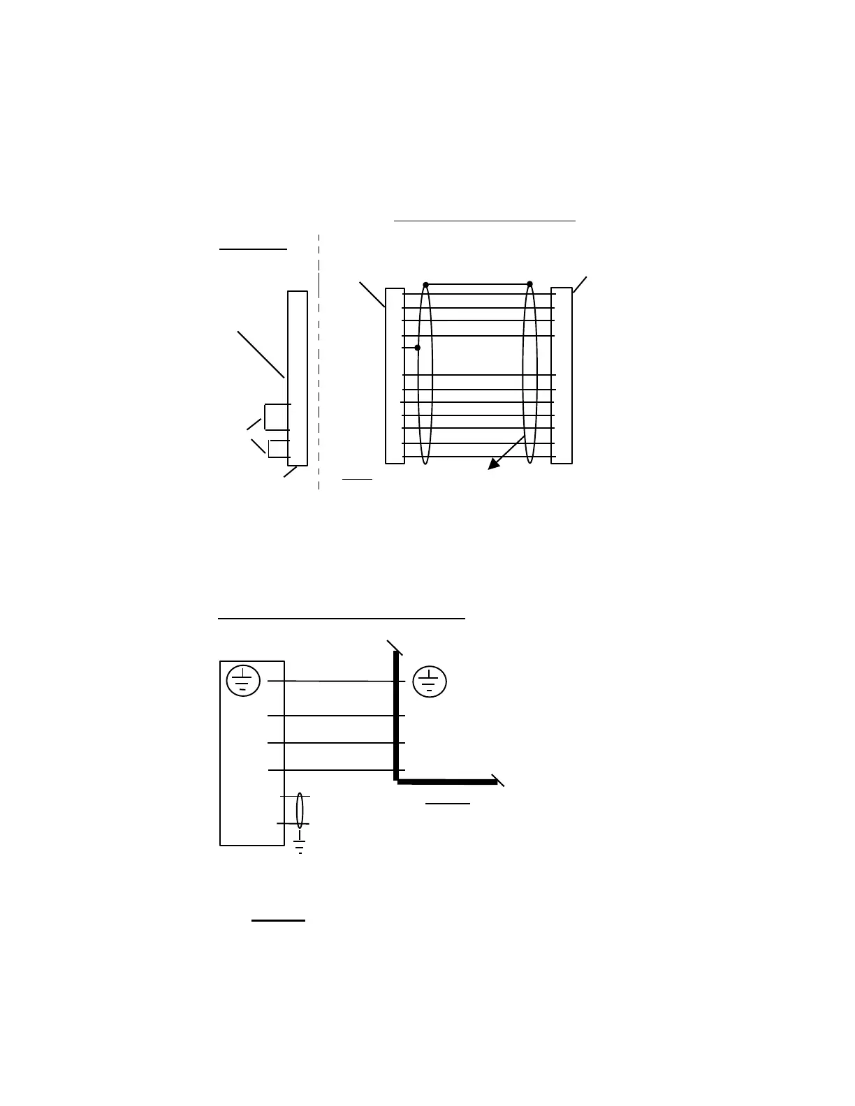
Wiring of Motor to Drive Power Cable
( Wire size dependent on Motor Type )
NOTE: For correct grounding, the Drive end Shield
of this cable should be connected to the Connector
Shell or the M5 hole on the top of the Module.
1-132
Motor to Drive connections
Connector assignment X311 and X313 (2
nd
Axis)
Connection of Power Leads – Drive to Motor