9
02.98
1-139
Siemens AG 1998 All Rights reserved 6SN1197–0AA00 02.98 Edition
SIMODRIVE 611 (PJ)
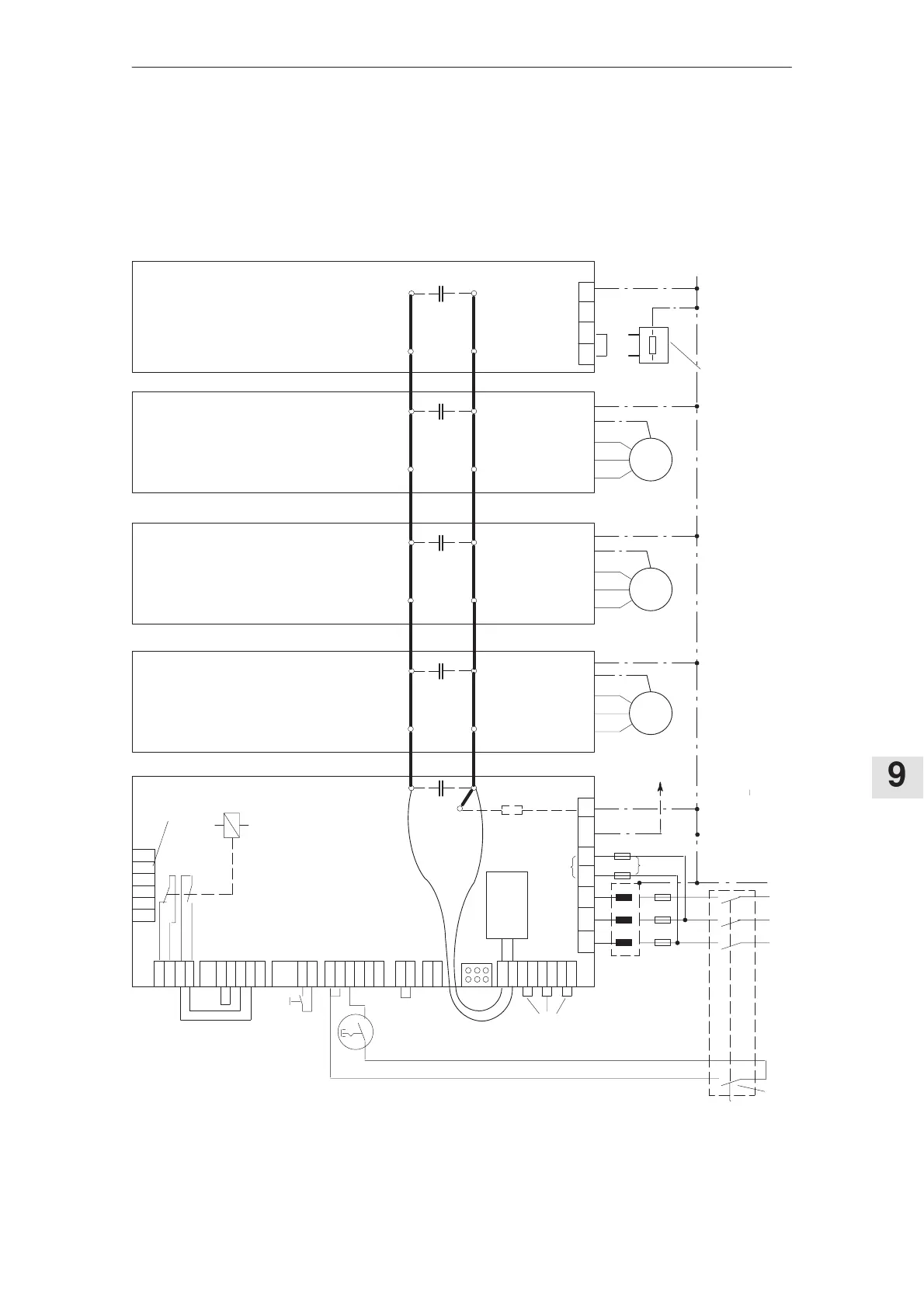
Supply failure buffering/retraction concept for
3–conductor connection
If the power supply is fed through P500, M500 at connector X181, it is not per-
missible to use a 6–conductor connection (electronics power supply connected
before the HF commutating reactor).
S1.5
!
S1.6
S1.4
S1.3
S1.2
S1.1
74
72
73.1
73.2
63
9
9
64
15
R
9
112
48
111
113
212
NS1
NS2
AS1
AS1
M500
P500
2U1
1U1
2V1
1V1
2W1
1W1
X121
X111
X141
X161
X171
X172
LEDs
X181
Pushbutton
contact
U1 V1 W1 L1 L2 X131PE
100k
5)
1)
M600
C
DCl.
NE–module
Drive 1 Drive 2
Drive n
Pulsed resistor
1R 2R 3R PE
P600
C
DCl.
C
DCl.
C
DCl.C
DCl.
2)
2)
2)
Auxiliary
power
supply
Drive 1
Drive 2
Drive n
Pulsed resistor
module
Leading
contact
L1 L2 L3 PESupply
...
Ready
relay
NE–module
4)
Necessary for
I/R 80/104kW
and 120/156 kW
(refer to Section 9.3)
Commutating
reactor, only for
I/R module
Main switch
M
Important!!
M M
Ext.Optional pulsed resistor
5)
Terminal 48 must be de–energized > 10 ms before the line contacts of the main switch open.
This means, e. g. a leading contact
6)
3)
to the NC
Figure 9-3
9.4 Supply failure buffering/retraction concept for 3–conductor connection
 Loading...


