4
02.98
1-66
Siemens AG 1998 All Rights reserved 6SN1197–0AA00 02.98 Edition
SIMODRIVE 611 (PJ)
For MSD/IMM digital and MSD/IMM analog: The sinusoidal currents are
RMS values.
1.I
n
continuous current
2.I
s6
current for max. 4 min for S6 duty cycle
3.I
max
peak current (duty cycle, refer to Section 4.2)
For feed drives, analog: Square–wave current,
the current values are the amplitude of the square–wave current.
For feed drives, digital: The sinusoidal currents are RMS values.
1.I
n
continuous current
2.I
max
peak current (duty cycle, refer to Section 4.2)
Pv
tot.
total module power loss
Pv
pipe
power loss which can be dissipated through pipe cooling
Pv
ext
power loss which can be dissipated through external cooling
Pv
int
power loss which is not dissipated via pipe or external cooling
This power loss remains in the cabinet
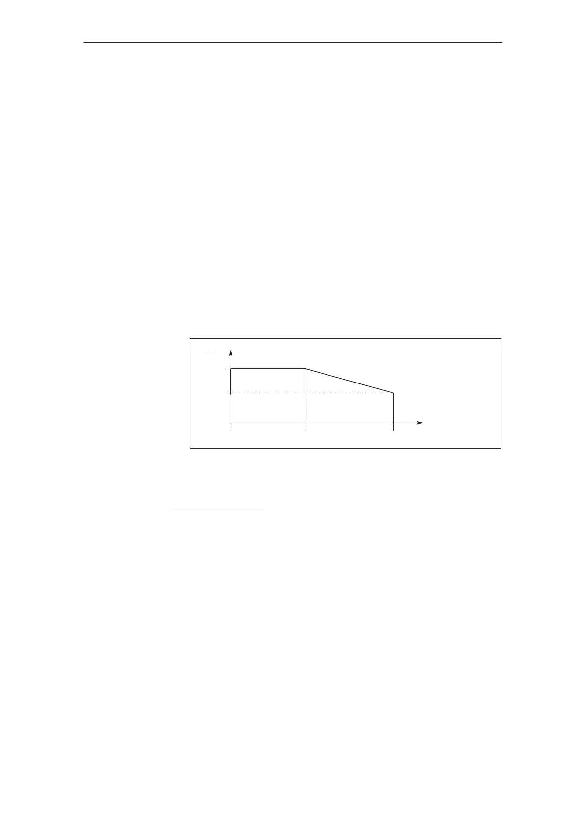
X1=Current reduction factor, current reduction from the inverter clock frequency
f
0
of the power transistors (refer to the technical data).
I
100 %
X1
In
Ambient temperature up to 40 C
0 %
f
0
80
f
1
[kHz]
Figure 4-2
Formula:
X=100% –
(100% – X1) (f
T
– f
0
)
8kHz – f
0
x = the reduction factor obtained [in %] for I
n
, I
s6
, I
max
f
T
= selected inverter clock frequency
å In
fT
= x In
f0
/100 %
å Is6
fT
= x Is6
f0
/100 %
å Imax
fT
= x Imax
f0
/100 %
Caution: The currents I
n
, I
s6
and I
max
must be reduced in the same way.
Definition of the
currents
Definition of the
powers
Current reduction
dependent on the
inverter clock fre-
quency
4.1 Technical data