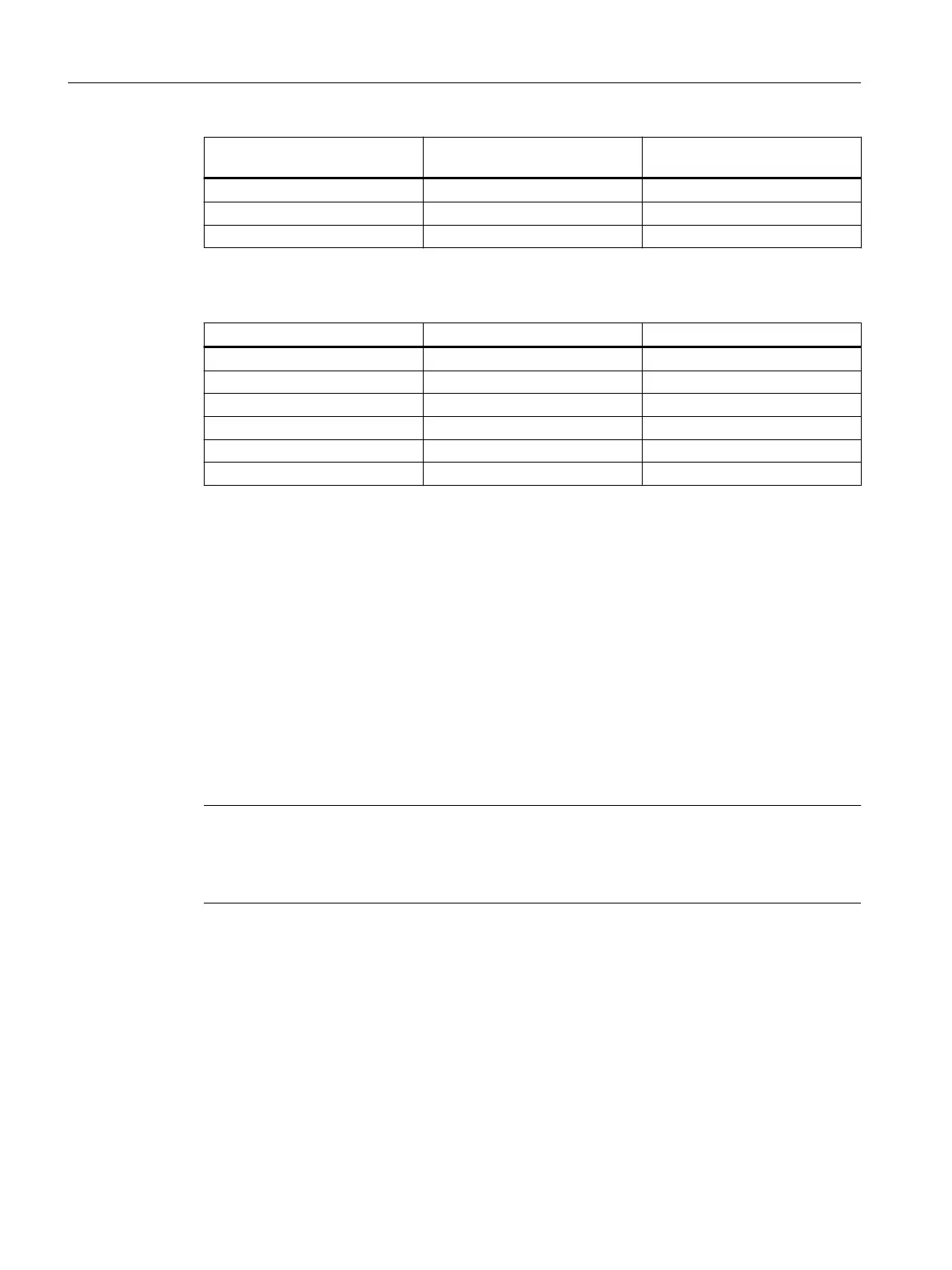
Installation altitude above sea
level in m
Air pressure in hPa Reduction factor
4000 606 0.775
5000 533 0.656
6000 469 0.588
Table 3-5 Typical DC link voltage of the SINAMICS converters
Network Infeed DC link voltage inV
230V 1AC unregulated/SLM/BLM 248
240V 3AC unregulated/SLM/BLM 307
400V 3AC unregulated/SLM/BLM 528
480V 3AC unregulated/SLM/BLM 634
400V 3AC ALM 600
480V 3AC ALM 720
In your engineered system, check whether the DC link voltage lies in the permissible range. If it is not,
reduce the DC link voltage; for example, by selecting an uncontrolled infeed or by reducing the line voltage.
Calculation example:
• Given:
– 1F☐2☐☐☐-☐☐F☐☐... motor → maximum permissible DC link voltage at 2000 m above
sea level: 720V (see table "Limit values for permissible DC link voltage...")
– Installation altitude: 3000 m above sea level: → reduction factor of the permissible DC link
voltage: 0.887
– Line voltage 3AC400V, with ALM (controlled infeed) --> DC link voltage 600V
• Calculate the permissible DC link voltage as follows:
– 0.877•720V=631V → 631V is higher than 600V. Reduction is not required.
Note
Observe the specications for the installation altitude of the converter
Observe the specications for the installation altitude of the converter used. The information
can be found in the manuals of the respective product.
As the DC link voltage is reduced, the converter output voltage also decreases. This reduces
the operating range in the M-n diagram.
The M-n diagrams are contained in the associated Conguration Manual.
Description of the motors
3.1Technical characteristics and ambient conditions
SIMOTICS S-1FT2 synchronous motors for SINAMICS S120
34 Operating Instructions, 12/2023, A5E50610821B AF