• Position the motor so that the cooling air can freely ow in and out.
• Make sure that no heated discharged air is drawn in.
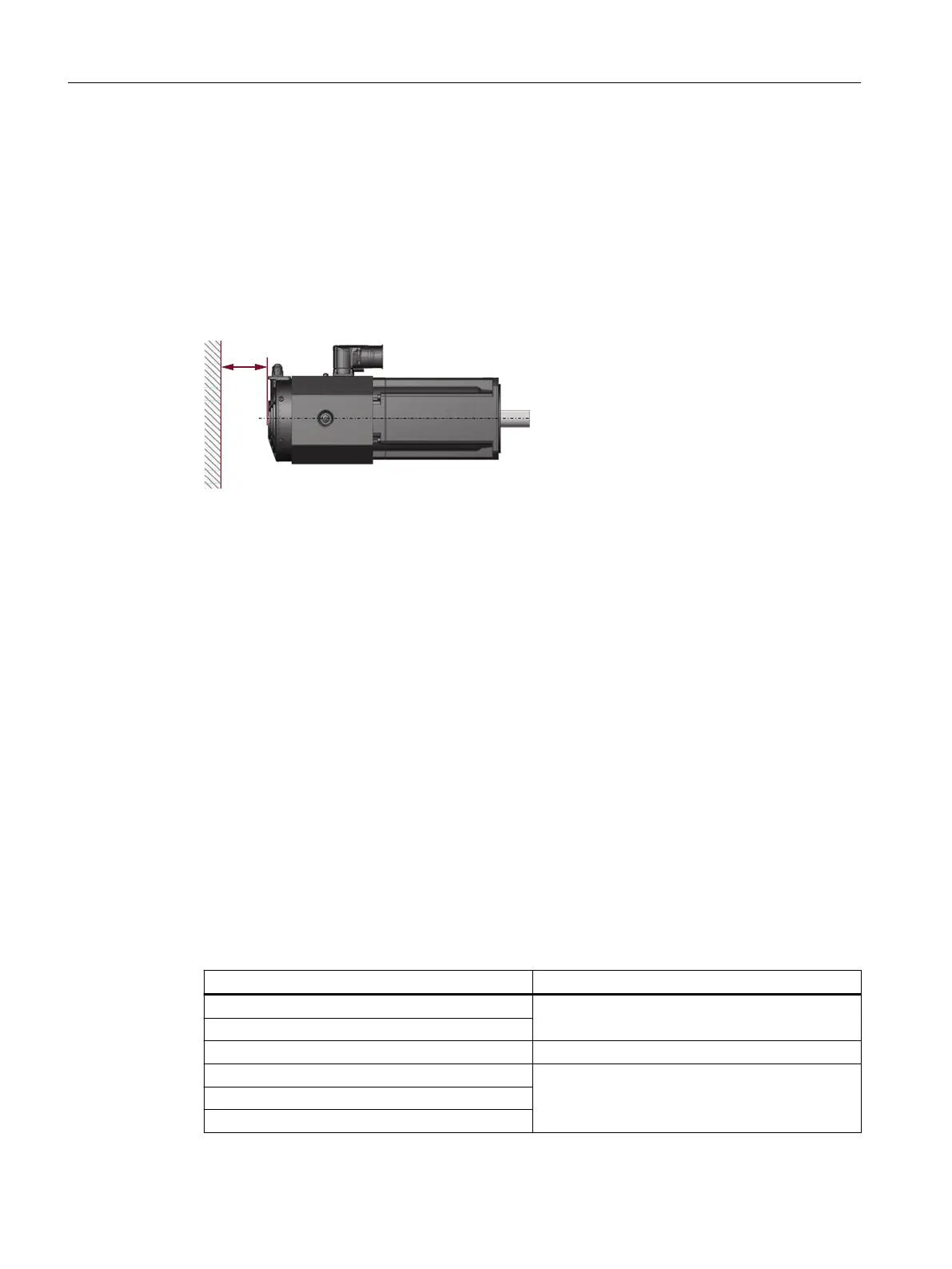
• Maintain the minimum clearance between the air intake and discharge openings and
adjacent components (see the "Minimum clearance" gure).
Minimum clearance to neighboring components or surfaces
s The minimum clearance is 30mm.
Figure4-1 Minimum clearance 1FT2, force-ventilated
Lifting and transporting the motor with forced ventilation
Information about lifting and transporting the motor is provided in Chapter "Transport
(Page59)"
Connecting the fan
Information about the electrical connection is provided in Chapter "Fan connection (Page90)".
4.5.3 Thermal mounting variants
Non-thermally insulated mounting
Some of the motor power loss is dissipated through the ange when the motor is connected to
the mounting surface.
• Observe the following mounting conditions for the specied motor data:
Shaft height Steel plate, width x height x thickness (in mm)
1FT2☐03 250 x 250 x 6
1FT2☐04
1FT2☐05 300x300x12
1FT2☐06
450 x 370 x 30
1FT2☐08
1FT2☐10
Mounting and options
4.5Cooling
SIMOTICS S-1FT2 synchronous motors for SINAMICS S120
48 Operating Instructions, 12/2023, A5E50610821B AF



 To Next Page