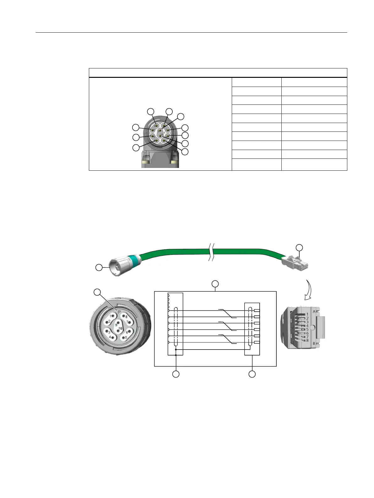
The connector pin assignment is as follows.
M17 signal connector, with DRIVE-CLiQ
1 TX-P
2 TX-N
3 -
4 -
5 RX-P
6 RX-N
7 -
8 -
9 24V
10 0V
The signal connectors can be rotated within a certain range.
More precise information on the angle of rotation is available in Chapter "Rotating the
connector on the motor (Page80)"
Connection diagram of the signal line for the 1F☐2 motor on the S120
The connection is made on a signal line with connector M17, 10-pin and RJ45 connector
p
1
591
59/
391
39/
7
7
7
#,
3%
391
39/
591
59/
7
"
#
#6
1,
:&
(/
1 M17 round connector, 10-pin 4 Pin assignment of M17 round
connector, 10-pin
2 RJ45/IP20 connector 5 Pin assignment of the RJ45 con‐
nector
3 Connection diagram P 0° coded
Connecting
7.3System integration
SIMOTICS S-1FT2 synchronous motors for SINAMICS S120
Operating Instructions, 12/2023, A5E50610821B AF 89