Mounting
4.3 Mounting instructions
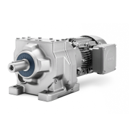
Planetary gearboxes for servomotors
Operating Instructions, 09/2020, A5E50494253B AA
39
4.3.2 Flange mounting and tightening torques for servomotors with planetary
gearbox
This chapter describes the designs and dimensions for flange mounting to a machine and the
associated tightening torques.
AG recommends an anaerobic adhesive to enhance the friction lock between flange
The tightening torque specified in this table are theoretical values.
They are based on the following:
• Calculated according to VDI 2230
• The friction coefficient for screws and mounting surfaces is μ = 0.10
• The yield strength reaches 90 %
• The tools used correspond to type II, Classes A and D according to ISO 6789
Setting values of the torque tools
The setting values are rounded off values that correspond to a generally applicable scale
division or setting options.
• Set these values precisely
Strength class of
M3 M4 M5 M6 M8 M10 M12 M14 M16 M18 M20 M22 M24
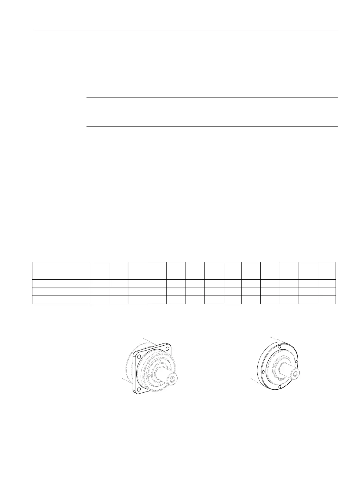
Flange designs at the gearbox output
Flange IM B5, e.g. NLC, SP+
Flange IM B14, e.g. NRB, NRK, NP