06.2006 Connecting-up
Siemens AG 6SE7087-6KP50
SIMOVERT MASTERDRIVES Operating Instructions 7-13
The following connections are provided on the control terminal strip:
♦ 4 combined digital inputs and outputs
♦ 2 additional digital inputs
♦ 1 analog input
♦ 1 analog output
♦ 24 V auxiliary voltage supply (max. 60 mA, output only!) for the
inputs.
If the digital inputs are supplied from an external 24 V supply, this must
be referenced to frame X101.2. Terminal X101.1 (P24 AUX) may not
be connected with the 24V supply.
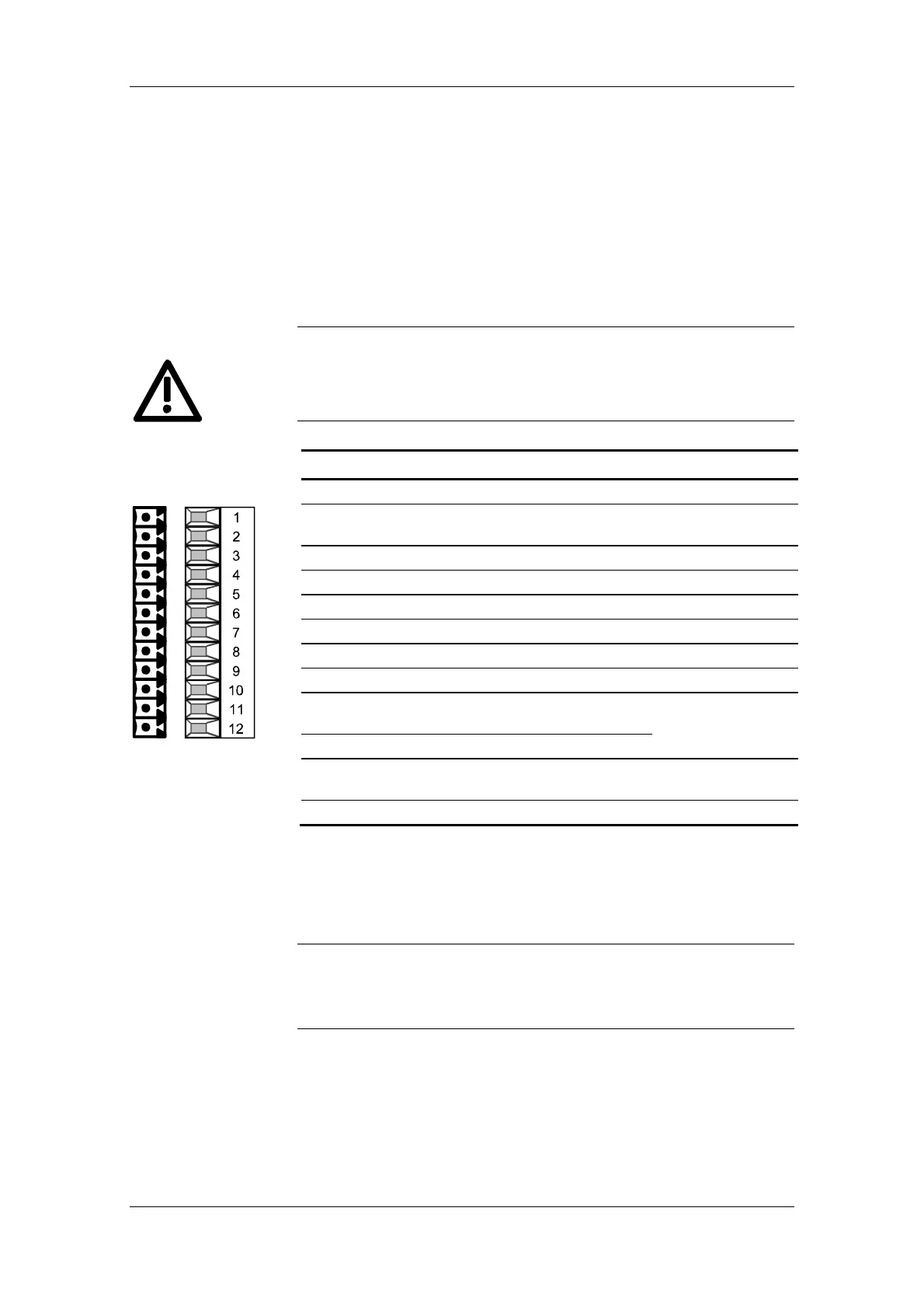
Terminal Designation Meaning Range
1 P24 AUX Aux. voltage supply DC 24 V / 60 mA
2 M24 AUX
Reference potential
choked
0 V
3 DIO1 Digital input/output 1 24 V, 10 mA / 20 mA
4 DIO2 Digital input/output 2 24 V, 10 mA / 20 mA
5 DIO3 Digital input/output 3 24 V, 10 mA / 20 mA
6 DIO4 Digital input/output 4 24 V, 10 mA / 20 mA
7 DI5 Digital input 5 24 V, 10 mA
8 DI6 Digital input 6 24 V, 10 mA
9 AI− Analog input −
11 bit + sign
differential input:
10 AI+ Analog input + ± 10 V / Ri = 40 kΩ
11 AO Analog output
8 bit + sign
± 10 V / 5 mA
12 M AO Ground analog output
Connectable cross-section: 0.14 mm² to 1.5 mm² (AWG 16)
Terminal 1 is at the top when installed.
Table 7-7 Control terminal strip
The outputs of the customer terminal can assume undefined states
during power up/board initialization/execution time overflow, unless a
specific response has been expressly defined (and implemented in the
hardware) for these periods.
X101 - Control
terminal strip
CAUTION
NOTE