Introduction
1.10 Abbreviations and circuit diagram symbols
Application document for functional safety STO, SS1 (ISO 13849-1)
Compact User Manual, 09/2016, A5E34871844AM
19
Abbreviations and circuit diagram symbols
K
AH[n]
Safety-related interface relay to control the armature contactor
Safety-related interface relay to control the field contactor
Relay, feedback signal E-Stop
Programmable digital output 2 2 = X177.21 (field contactor control)
Programmable digital output 3 = X177.22 (feedback signal E-Stop active)
Programmable digital input 4, X177.15 (to select OFF3 = fast stop)
Phoenix Contact, PSR-SPP-24DC/FSP/1X1/1X2 - 2981981
Phoenix Contact, PR1-RSC3-LDP-24DC/2X21AU - 2834520
24 V supply via X177.9 or X177.10
24 V ground via X177.23 or X177.24
Maximum supply voltage, 250 V
AC
L
AH1
, N
AH1
Maximum armature contactor supply voltage 250V AC/DC 5A
Observe the load curve and derating of the K
AH
L
FH
, N
FH
Maximum field contactor supply voltage 250V AC/DC 5A
Observe the load curve and derating of the K
L
AH[n]
, N
AH[n]
Maximum armature contactor supply voltage 250V AC/DC 5A
Observe the load curve and derating of the K
AH[n]
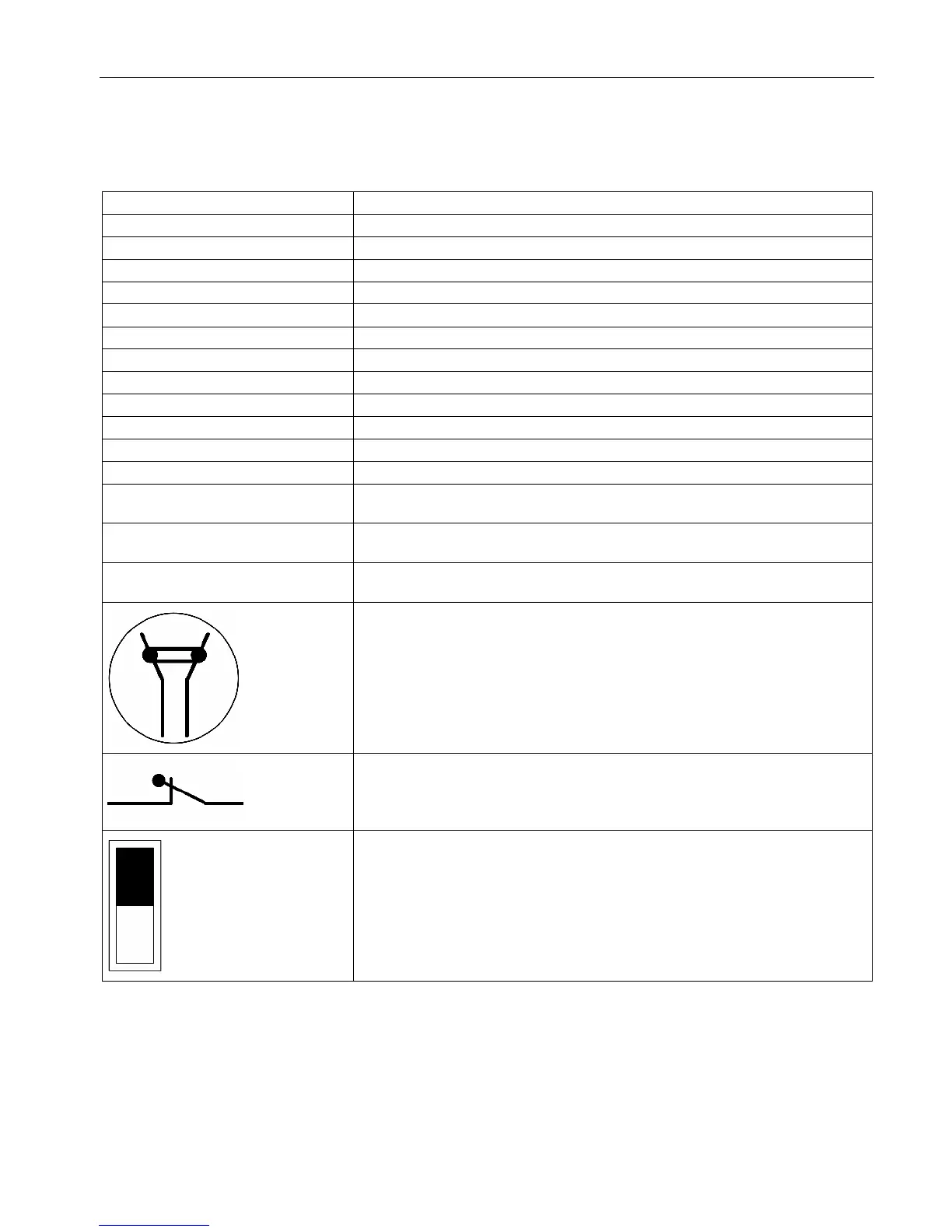
Positively-driven contacts = combination of NO and NC contacts is designed so
that they can never be simultaneously closed
Mirror contact = auxiliary NC contact that cannot be closed simultaneously with a
main NO contact.
Switch position = black

 Loading...


