Design of the frequency converter
2.3 Power Module
Converter with Control Units CU230P-2; CU240B-2; CU240E-2
Getting Started, 11/2013, A5E32885834B AA
19
The following accessories are available for the converter:
● Operator Panel for commissioning and diagnostics (Basic Operator Panel BOP-2 or
Intelligent Operator Panel IOP).
● Memory card for backing up the settings of the converter on a replaceable medium.
● Shield connection kit for optimum shield support of the connected cables. For further
information, see Overview of the shield connection kits
(http://support.automation.siemens.com/WW/news/en/67225884)
● Line filter for achieving a higher radio interference suppression class.
● Line reactor for protecting the converter in harsh industrial networks.
● Output reactor for protecting the converter when motor cables > 50 m (shielded) or >
100 m (unshielded) are used.
● Sine-wave filter for protecting motors which are not suitable for converter operation and
for motor cables up to 300 m.
● Braking resistor for dynamic braking of the motor.
● Brake Relay for controlling a motor holding brake.
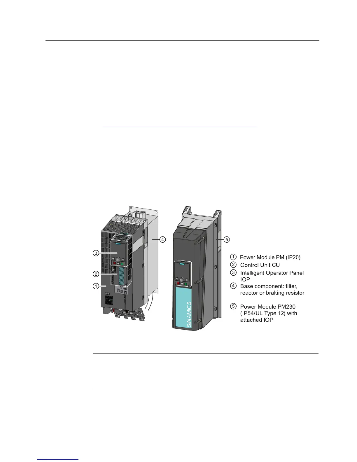
Figure 2-1 Design of the converter (example)
Note
Converters with IP55 degree of protection
In order to comply with degree of protection IP55, the converter has to be operated eit

 Loading...


