Converter with Control Units CU230P-2; CU240B-2; CU240E-2
Getting Started, 11/2013, A5E32885834B AA
23
Installing the Power Module
Danger of death caused by high leakage currents when the external protective conductor is
interrupted
The inverter conducts high leakage currents > 3.5 mA via the protective conductor. When
the protective conductor is interrupted, touching live components can result in electric
shock, which can lead to death or serious injuries.
• Connect a protective conductor, which satisfies at least one of the following conditions,
to the inverter:
– The protective conductor is routed so that it is protected against mechanical damage.
Cables routed in control cabinets or enclosed machine enclosures are considered to
be adequately protected.
– The protective conductor routed as an individual conductor has a cross-section of
≥ 10 mm² Cu.
– In a multi-core cable the protective conductor has a cross-section of ≥ 2.5 mm² Cu.
– Two parallel protective conductors with the same cross-section are installed.
– The protective conductor corresponds to the local regulations for equipment with
increased leakage current.
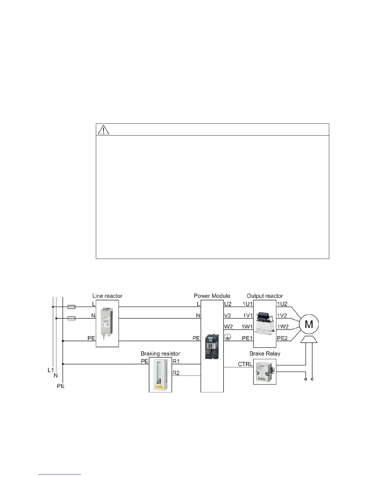
Connecting the Power Module to the motor and power supply
Figure 3-1 Connecting the PM340 1AC Power Module

 Loading...


