Commissioning
4.2 Commissioning with BOP-2 operator panel
SINAMICS G120C converter
Getting Started, 04/2014, FW V4.7, A5E34264105B AA
39
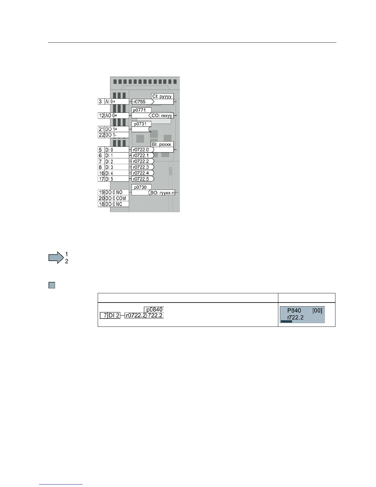
Changing the function of individual terminals
The function of the terminal is def
interconnection in the inverter:
The inverter writes every input signal into a readable
parameter. Parameter r0755 makes the signal of the
analog input available, for example.
To define the function of the input, the appropriate
parameter (connector CI or BI) must be set to the
parameter number of the input.
Every inverter output is represented by a parameter
that can be written to. The value of parameter p0771
defines the analog output signal, for example.
To define the output function, you must set the
parameter number of the output to the parameter
number of the matching signal (binector CO or BO).
In the parameter list, the abbreviation CI, CO, BI or BO as
prefix indicates as to whether the parameter is available as
signal fo
r the function of the terminal.
Defining the function of a digital input
Procedure
To define the function of a digital input, proceed as follows:
1. Select the function marked using a BI parameter.
2. Enter the parameter number of the required digital input 722.x into the BI parameter.
You have defined the digital input function.
Example: You want to switch on the motor using DI 2.
When switching over the master control of the inverter (for example, if you select default
setting 7), you must select the correct index of the parameter:
● Index 0 (e.g., P840[00]) applies for the interface assignment on the left side of the macro
illustration.
● Index 1 (e.g., P840[01]) applies for the interface assignment on the right side of the
macro illustration.

 Loading...


