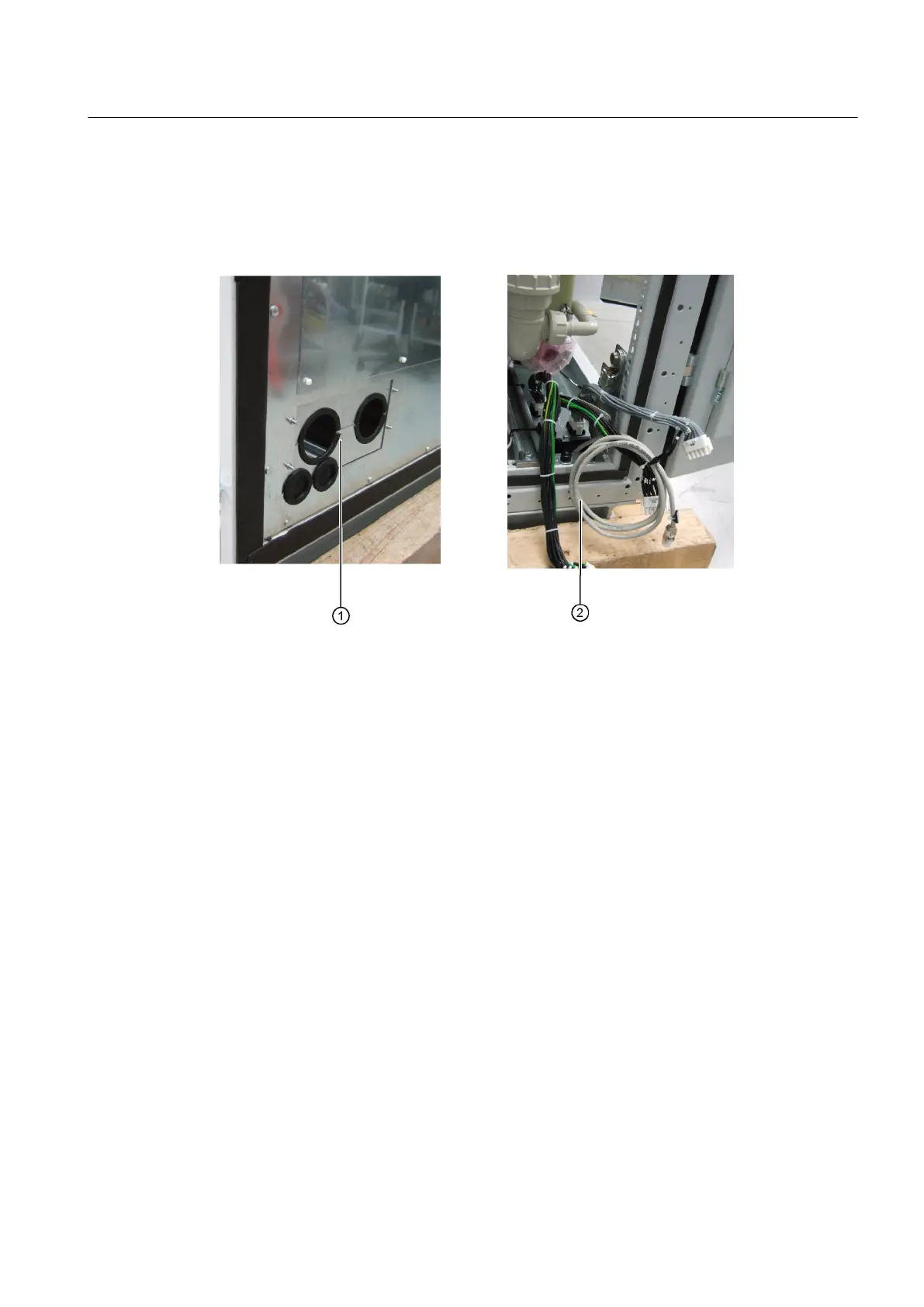
Route the interface cables ② through the openings ①. Connect the cabinet interface sockets
using cables as shown in the circuit diagram. Route the fiber-optic cable carefully without
kinking the cable.
Detailed information is provided in the converter circuit diagram.
Figure 5-3 Example: Connecting the interface cable
5.4.2 Connect the DC cable
To connect the DC link, you must connect the DC cable and the yellow cable designated "KM"
to the respective connection busbars. The positions of the connections are shown in the layout
diagrams. Note the designations of the cables and connections. More detailed information is
available in the circuit manual.
Screw the DC cable to the terminal bars as follows:
1. Place a DIN 6796 spring washer on the M12 DIN EN ISO 4014 screw.
2. Place the cable lug on the screw. Insert the screw through the hole in the terminal bar.
3. Place an ISO 7089 washer and an SN60727 spring washer at the end of the screw.
Alternatively, instead of the washer and the spring washer, you can use a spring washer
according to DIN 6796.
Assembly
5.4 Connecting cabinets
SINAMICS SH150 6SL3805
Operating Instructions 05/2020 61
 Loading...


