03.06
4.3 NCU module interfaces
4-52
© Siemens AG, 2006. All rights reserved
SINUMERIK 840D Configuring Manual NCU (PHD) – 03.06 Edition
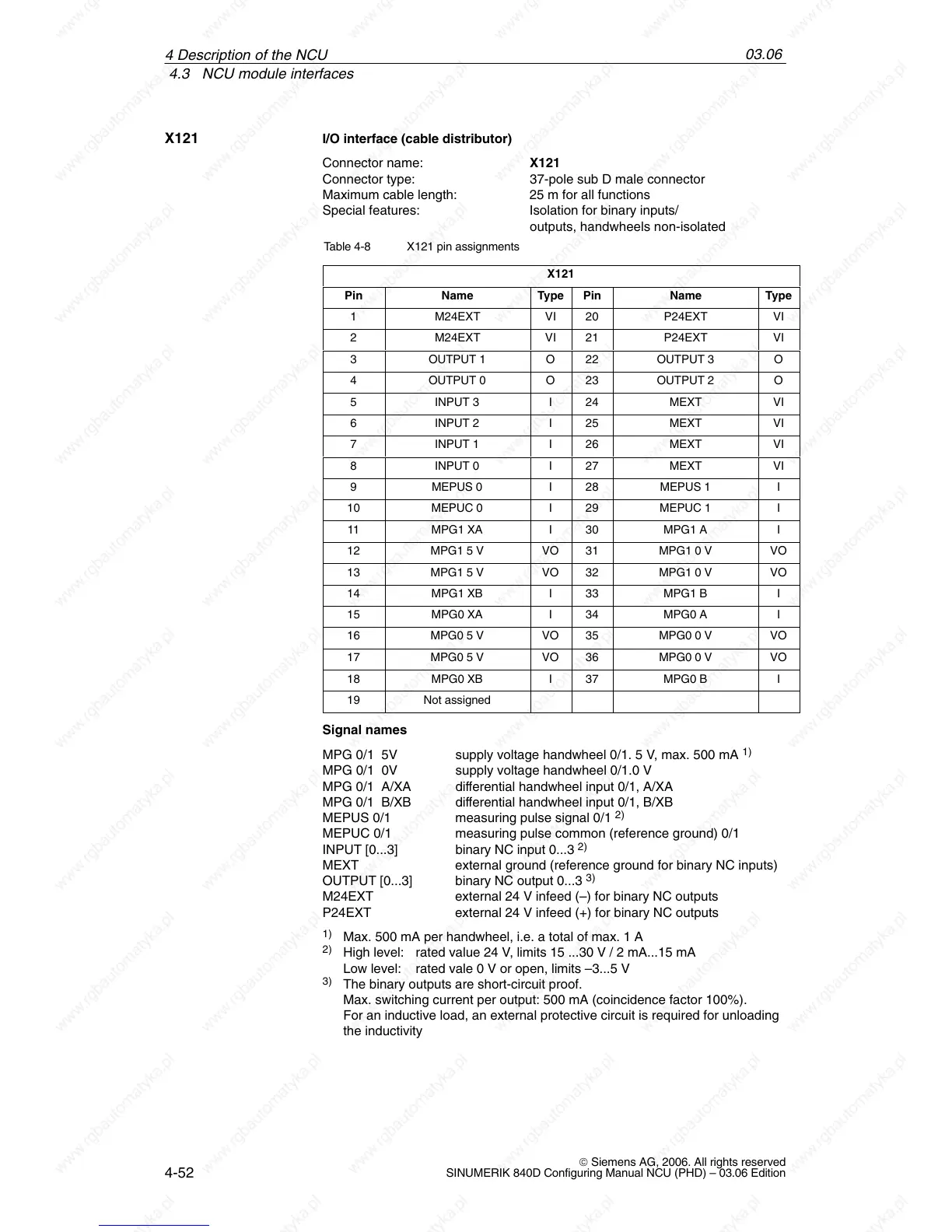
I/O interface (cable distributor)
Connector name: X121
Connector type: 37-pole sub D male connector
Maximum cable length: 25 m for all functions
Special features: Isolation for binary inputs/
outputs, handwheels non-isolated
Table 4-8 X121 pin assignments
X121
Pin Name Type Pin Name Type
1 M24EXT VI 20 P24EXT VI
2 M24EXT VI 21 P24EXT VI
3 OUTPUT 1 O 22 OUTPUT 3 O
4 OUTPUT 0 O 23 OUTPUT 2 O
5 INPUT 3 I 24 MEXT VI
6 INPUT 2 I 25 MEXT VI
7 INPUT 1 I 26 MEXT VI
8 INPUT 0 I 27 MEXT VI
9 MEPUS 0 I 28 MEPUS 1 I
10 MEPUC 0 I 29 MEPUC 1 I
11 MPG1 XA I 30 MPG1 A I
12 MPG1 5 V VO 31 MPG1 0 V VO
13 MPG1 5 V VO 32 MPG1 0 V VO
14 MPG1 XB I 33 MPG1 B I
15 MPG0 XA I 34 MPG0 A I
16 MPG0 5 V VO 35 MPG0 0 V VO
17 MPG0 5 V VO 36 MPG0 0 V VO
18 MPG0 XB I 37 MPG0 B I
19 Not assigned
Signal names
MPG 0/1 5V supply voltage handwheel 0/1. 5 V, max. 500 mA
1)
MPG 0/1 0V supply voltage handwheel 0/1.0 V
MPG 0/1 A/XA differential handwheel input 0/1, A/XA
MPG 0/1 B/XB differential handwheel input 0/1, B/XB
MEPUS 0/1 measuring pulse signal 0/1
2)
MEPUC 0/1 measuring pulse common (reference ground) 0/1
INPUT [0...3] binary NC input 0...3
2)
MEXT external ground (reference ground for binary NC inputs)
OUTPUT [0...3] binary NC output 0...3
3)
M24EXT external 24 V infeed (–) for binary NC outputs
P24EXT external 24 V infeed (+) for binary NC outputs
1)
Max. 500 mA per handwheel, i.e. a total of max. 1 A
2)
High level: rated value 24 V, limits 15 ...30 V / 2 mA...15 mA
Low level: rated vale 0 V or open, limits –3...5 V
3)
The binary outputs are short-circuit proof.
Max. switching current per output: 500 mA (coincidence factor 100%).
For an inductive load, an external protective circuit is required for unloading
the inductivity
X121
4 Descri
 Loading...


