03.06
5.1 Single I/O module
5-70
© Siemens AG, 2006. All rights reserved
SINUMERIK 840D Configuring Manual NCU (PHD) – 03.06 Edition
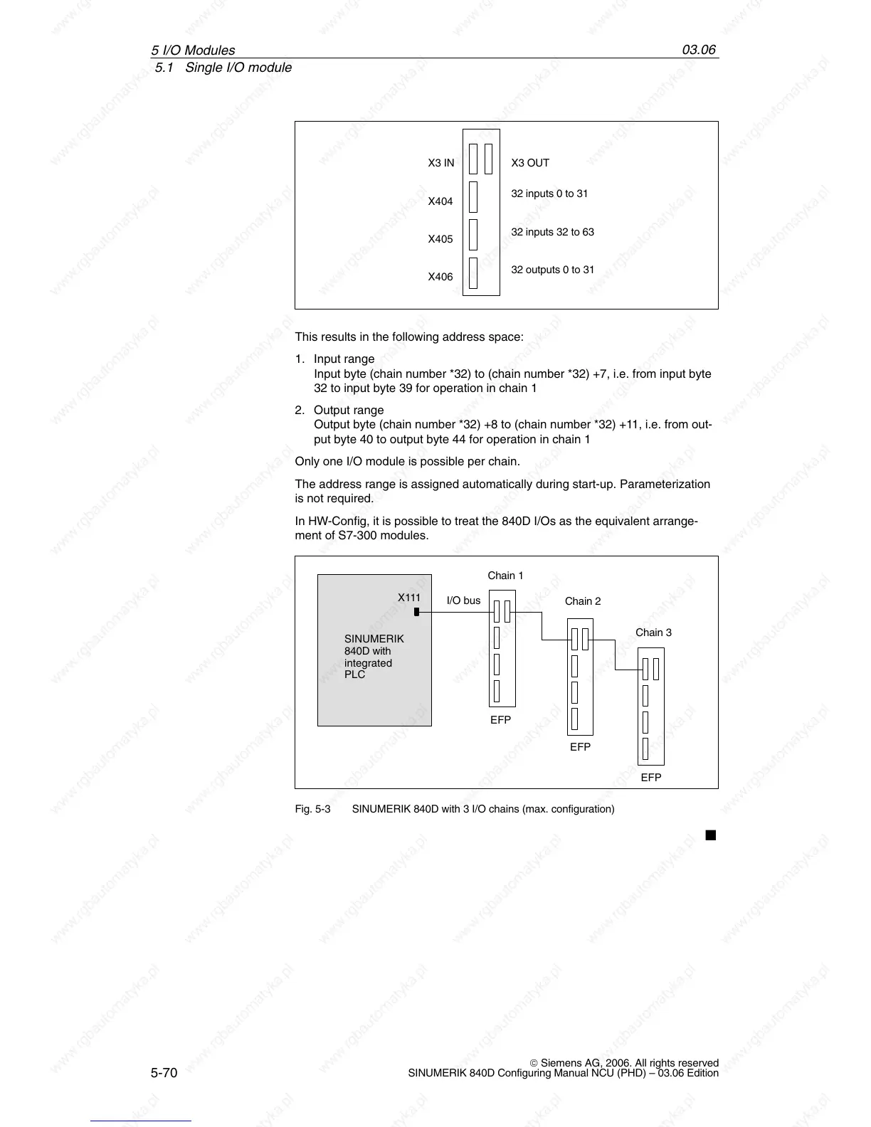
X404
X405
X406
X3 IN X3 OUT
32 inputs 0 to 31
32 inputs 32 to 63
32 outputs 0 to 31
This results in the following address space:
1. Input range
Input byte (chain number *32) to (chain number *32) +7, i.e. from input byte
32 to input byte 39 for operation in chain 1
2. Output range
Output byte (chain number *32) +8 to (chain number *32) +11, i.e. from out-
put byte 40 to output byte 44 for operation in chain 1
Only one I/O module is possible per chain.
The address range is assigned automatically during start-up. Parameterization
is not required.
In HW-Config, it is possible to treat the 840D I/Os as the equivalent arrange-
ment of S7-300 modules.
SINUMERIK
840D with
integrated
PLC
X111
Chain 1
Chain 3
Chain 2
I/O bus
EFP
EFP
EFP
Fig. 5-3 SINUMERIK 840D with 3 I/O chains (max. configuration)
5 I/O Modules
 Loading...


